 접촉기,회로 차단기,감지기,인코더,PLC,변환기

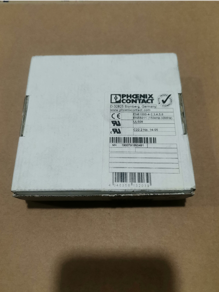

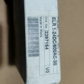
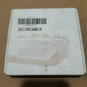
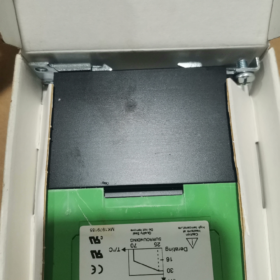
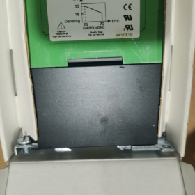
피닉스컨택트 ELR1-24DC-600AC-30, 주문 번호. 2297154
- Complete Model Decoding
모델: ELR1-24DC-600AC-30
- ELR1: Series → ELR1 single-phase
- 1 single-phase electronic load 계전기
- (solid-state contactor, contactless switch, 모터 부하에 적합)
- 24DC: Control side supply / drive voltage: 24 DC에서
- 600교류: Rated operating voltage of main circuit: AC 0…600 V
- 30: 정격 연속 동작 전류: 30 에이
- 2297154: Official unique 피닉스 Contact order number
전체 제품 이름: ELR 1-24DC/600AC-30 Solid-State Contactor
- 핵심 전기 매개변수
| 목 | 사양 |
| 주문 번호. | 2297154 |
| 제어 전압 | 24 DC에서 (허용 범위: 19.2~30 V DC) |
| 주회로 전압 | AC 0~600 V, 50/60 헤르츠 |
| 정격 부하 전류 | 30 에이 (저항 부하) |
| Applicable Load Type | Single-phase AC loads; 팬, 발열체, small single-phase motors |
| Switching Component | Bidirectional triac (비접촉식) |
| 스위칭 주파수 | Much higher than mechanical contactors, suitable for frequent switching |
| 격리 | Optoelectronic isolation; galvanic isolation between control circuit and main circuit |
| 장착 유형 | 35 mm DIN 레일 장착 |
| 연결 | 나사식 터미널 연결 |
| 주변 작동 온도 | -20 ℃ ~ +60 ℃ (위에 필요한 경감 40 ℃) |
- 주요 특징
✅ No mechanical contacts, no electric arcs, 저소음, 연장된 서비스 수명, ideal for frequent start-stop operation
✅ Built-in overvoltage absorption circuit to suppress inductive load surge
⚠️ Important Restriction: Single-phase solid-state relay. Not for direct control of three-phase loads; only applicable to single-phase AC loads
⚠️ For inductive loads (모터, 코일), sufficient current margin is required; 30% current derating is recommended
- 핀 / 터미널 정의
A1 / A2: Control terminals for 24 DC에서
A1(+), A2(-)
엘 / N: AC input terminals of main circuit
밖으로: Load output terminal
- 일반적인 애플리케이션 시나리오
Control of electric heaters inside industrial control cabinets
Frequent start-stop of single-phase fans and conveyor motors
Temperature control loops for packaging machinery, test equipment and ovens
AC loads requiring low-noise, maintenance-free switching
- 대안 & Same-Series References
- Lower-current variants in the same series: ELR1-24DC-600AC-10 (10 에이), ELR1-24DC-600AC-20 (20 에이)
- For three-phase solid-state switches: Refer to ELR3 series (three-phase solid-state contactors)
- Competitor equivalents: Schneider SSP series, Omron G3PA single-phase solid-state relays
- 조달 참고 사항
Distinguish model suffixes: Do not confuse ELR1 (단상) / ELR3 (삼상)
Use order number 2297154 strictly to avoid delivery of other current ratings
Solid-state components generate significant heat; sufficient clearance for heat dissipation is required for dense installation inside cabinets
Application Scenarios — Phoenix Contact ELR 1-24DC/600AC-30 (Order No.2297154)
Product Overview Recap
Single-phase solid-state contactor (contactless SSR)
제어: 24 DC에서; 주회로: ≤600 V AC, 등급 30 에이; DIN 레일 장착; optoelectronic isolation; bidirectional triac output; optimized for frequent switching of single-phase AC loads
핵심 장점: Arc-free, 기계적 마모 없음, 저소음, high-speed frequent switching. 한정: Self-heating, current derating mandatory for inductive loads.
Critical Premise: Only supports single-phase AC loads; cannot directly drive three-phase motors
- General Standard Industrial Scenarios
1.1 Resistive Heating Loads (가장 일반적인 응용 프로그램)
- Control of heating tubes in ovens, tunnel furnaces and thermal processing equipment
- Heating circuits for injection molding and extruder barrels
- Industrial thermostats, hot air blowers and duct electric heaters
- Heating elements of heat-sealing machines and hot stamping equipment in packaging machines
✅ Advantage: PID high-frequency continuous switching by temperature controllers rapidly wears contacts of mechanical contactors; ELR1 perfectly fits this working condition
1.2 Single-Phase Fans & 슬리퍼 (유도 부하)
Application requirement: 25%~30% current derating for load selection
- Control cabinet cooling fans, industrial exhaust fans and ducted single-phase fans
- Small single-phase centrifugal pumps, circulating water pumps and fume exhaust fans
- Air supply units for drying equipment
⚠️ Note: Large inrush current upon motor startup; recommended actual load ≤20~22 A for the 30 모델
1.3 Lighting Loads
- High-power halogen lamp banks and infrared heating lamp arrays in workshops
- High-power lighting arrays in test laboratories
❌ Not recommended: LED drivers and electronic ballast loads (high inrush current; RC snubber circuit is recommended)
- Industry-Specific Field Applications
▶ Packaging Machinery
- Heating control for heat shrink tunnels
- Actuation of heat-seal bars on vertical / horizontal packaging machines
- Single-phase drive motors on conveying lines and hot air drying systems
▶ Plastics & 고무 기계
- Heating rod control for each temperature zone of extruders and pelletizers
- Start-stop control of heating circuits for mold temperature controllers
▶ HVAC & Environmental Test Equipment
- Heaters for high-low temperature test chambers and constant temperature & humidity chambers
- Hot air circulation systems for purification equipment
- Heating modules of industrial dehumidifiers
▶ New Energy & Lithium Battery Production Lines
- Heating control for electrode drying ovens
- Hot air devices for dust removal equipment
이점: No sparks for dust-free workshops (the device itself is NOT explosion-proof; explosion-proof enclosure is mandatory for hazardous areas)
▶ Food & 제약 장비
- Electric heating systems for food baking lines and sterilization equipment
- Hot air drying units for cleaning equipment
이점: Contactless operation prevents metallic dust generation, meeting operation requirements for cleanrooms
▶ Automated Test Equipment
- Switching of high-power loads on aging test benches
- Adjustable AC load switching devices in laboratories
- Cluster control of high-power AC solenoid coils
- 적용할 수 없는 시나리오 (Selection Red Lines)
- ❌ Direct control of three-phase asynchronous motors (ELR1 is single-phase SSR; only controls one phase. Strictly prohibited as main three-phase switch. Select ELR3 series for three-phase loads)
- ❌ Frequent startup of high-power single-phase compressors (severe startup inrush current may cause triac breakdown)
- ❌ Applications relying on the device for long-term overload & 단락 보호 (solid-state relays have poor short-circuit withstand capability; 회로 차단기 / fuses must be installed upstream)
- ❌ Unprotected outdoor open-air installation (must be fitted inside control cabinets)
- ❌ High-frequency high-voltage inductive loads without RC snubber circuits
- Recommended Supporting Configuration for On-Site Deployment
- 유도 부하 (모터, 코일): Parallel Phoenix Contact RC absorption modules to suppress back EMF
- Multiple units mounted side-by-side on DIN rail: Maintain minimum clearance ≥10 mm between adjacent devices; current derating required when cabinet ambient temperature>45 ℃
- Upstream protection: Deploy gG fuses; circuit breakers alone cannot provide reliable short-circuit protection
- Preferred component for PID temperature control systems; switching frequency can reach several cycles per second, service life far exceeding mechanical contactors
Mounting Specification — Phoenix Contact ELR 1-24DC/600AC-30 (2297154)
- Standard Mounting Form
표준 장착: Snap-on installation on 35 mm DIN 레일 (TH35-7.5)
- Integrated DIN rail locking clip on device rear side; no additional brackets required
- Mandatory mounting orientation: 수직 설치 (terminals facing up/down; cooling fins arranged vertically)
❌ Horizontal side mounting & inverted installation are forbidden! Horizontal placement blocks natural convection cooling, leading to overheating shutdown and triac damage.
- 설치 & Dismantling Procedures
- Hook the upper clip onto the DIN rail;
- Press down the main body until an audible “딸깍 하는 소리” confirms the lower clip locks onto the rail;
- 제거: Pry open the bottom clip with a flat screwdriver and lift the device upwards.
- Thermal Clearance Requirements (비판적인! 30 A solid-state contactors generate considerable heat)
Single Independent Installation
Vertical clearance (맨 위 & 맨 아래): ≥50 mm ventilation space
Lateral clearance: ≥10 mm if adjacent space is vacant
Multiple Units Mounted Side-by-Side on the Same DIN Rail
Minimum clearance between adjacent devices: ≥10 mm
Zero-clearance tight arrangement is prohibited
Maintain ≥15 mm clearance if cabinet temperature>40 ℃
For large-scale continuous installation, forced air cooling via cabinet axial fans is recommended
- 배선사양 (나사 터미널)
터미널 할당
A1(+), A2(-): 24 V DC control circuit
엘, 밖으로: Main circuit for single-phase AC loads
Wiring Parameters
- 터미널 유형: 풀림 방지 나사 단자
- Applicable conductors:
솔리드 단일 코어 와이어: 0.5~10 mm²
Stranded flexible wire: Crimp lugs are recommended
- Recommended tightening torque: 1.2~1.5 N·m
⚠️ Insufficient torque → excessive heating; excessive torque → thread slipping or terminal base cracking.
Wiring Layout Suggestion
Separate routing for control cables (A1/A2) and high-power cables (L/OUT) 전자기 간섭을 줄이기 위해
Minimize length of power wiring to reduce voltage drop and heat generation
- Ambient Operating Boundary Conditions
- 설치 위치: Inside control cabinets, IP20 보호 등급
❌ Direct exposure to open air; 먼지를 피하다, moisture and condensation contacting the device
- Permissible operating temperature: -20 ℃ ~ +60 ℃
Current derating is mandatory when ambient temperature>40 ℃
- Avoid these installation positions:
Directly above transformers, power resistors and other heat-generating components
Poorly ventilated dead zones inside cabinets
Locations with persistent strong vibration (continuous vibration loosens terminal screws)
- Optional Heat Dissipation Accessories
For continuous full-load operation in enclosed cabinets, DIN rail-mounted aluminum heat sinks can be attached to the rear of the device to reduce housing temperature.
No heat sink supplied as standard; cooling relies on integrated housing fins for natural convection.
- 엄격히 금지된 작업
- Do not suspend the device by cables; all mechanical load shall be supported by the DIN rail
- Do not block cooling fins on sides and rear surface
- Do not connect multiple ELR1 units in parallel for current sharing (inconsistent on-resistance causes uneven current distribution and burnout)
- Do not install contactors / circuit breakers tightly adjacent to solid-state contactors without heat clearance
Standard Description for Engineering Drawings
The ELR1-24DC/600AC-30 shall be vertically mounted on TH35 standard DIN rail. Lateral clearance between adjacent devices ≥10 mm. Separate routing for control and power circuits. 단자 조임 토크: 1.2~1.5 N·m. Ensure adequate natural ventilation for heat dissipation.



NH42-63-318x560.png "CHINT PC형 자동절환스위치 (ATS)NH42-63/4SZ")



