 접촉기,회로 차단기,감지기,인코더,PLC,변환기

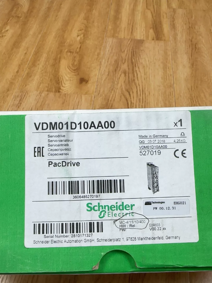

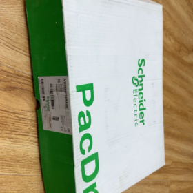
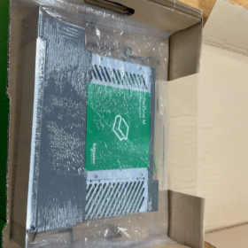
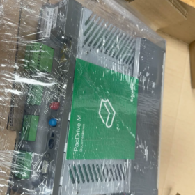
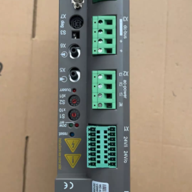
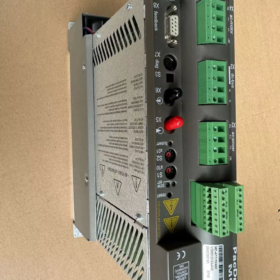
성명: 슈나이더 PacDrive VDM01D10AA00
Old part number: MC-4/11/10/400 (13130247)
Brand background: Originally ELAU (독일), later acquired by Schneider Electric → PacDrive MC-4 Series 서보 드라이브
기원: 독일
⚠️ Product Status: Discontinued by manufacturer, no new production. Only new surplus stock and used second-hand units available on the market.
주요 사양
- 전원공급장치
3-phase 380~480V AC (400V 클래스)
- 정격 출력 전류
10A continuous
- 호환 모터
ELAU / PacDrive SH / SM series synchronous servo motors, suitable for motors approx. 2~4kW (depends on motor back EMF matching)
- 필드버스
SERCOS II (classic real-time bus for PacDrive multi-axis synchronization)
- 인코더 인터페이스
Supports EnDat, Hiperface and other ELAU servo feedback protocols
- 보호 등급: IP20 (cabinet mounting)
- 작동 온도: 0~+50℃ (inside electrical cabinet)
모델 디코딩 (VDM01D10AA00)
VDM01: Drive hardware platform series
디: 400V three-phase high voltage variant
10: Rated continuous current 10A
AA00: Standard firmware, no special custom options
Typical Application Industries
포장 기계, blow molding machines, food processing equipment, printing machinery, lithium battery front-end production equipment and other multi-axis synchronized machinery (widely equipped on legacy machines with ELAU PacDrive system)
중요 사항
- Cannot be directly replaced by Lexium28/32 or other newer Schneider servo drives
This is a dedicated PacDrive servo using the SERCOS bus. Its control architecture and communication protocol are completely different from general Lexium servo ranges. If the machine controller is PacDrive C400/C600, replacement is only possible with identical VDM series drives.
- Directly interchangeable model: VDM01D10AA00 ↔ MC-4/11/10/400, 하드웨어와 완전히 호환 가능.
- 소싱: Only available via automation spare parts suppliers (new surplus / used refurbished units); Schneider official has no stock and no further production.
Cross Reference within the Series (for replacement selection)
VDM01U05AA00:230다섯 / 5에이
VDM01U10AA00:230V /10A
VDM01D10AA00:400V /10A (이 모델)
VDM01D22AA00:400V /22A
Schneider ELAU VDM01D10AA00 (MC-4/11/10/400)
- Common Fault Code List (PacDrive SERCOS System, alarms read via C400/C600 Controller)
메모: Fault codes are reported by PacDrive master controller. The drive itself only has ERR / BusErr LEDs; no digital display.
🔌 Power Hardware Faults (Most frequent on second-hand drives)
| 오류 코드 | Fault Name | 설명 & 문제 해결 |
| 107 | Over-current | IGBT module failure, motor short circuit, output earth short; priority inspection item for used units |
| 113 | Bleeder defective | Internal braking transistor damaged; typically triggered during deceleration |
| 115 | Gate-power failure | Inverter gate drive power supply fault, drive board damage; alarm occurs immediately after power-up |
| 119 | Output short / 지락 | U/V/W phase-phase short or earth leakage; typical symptom of IGBT breakdown |
| 120 | Output stage overload | 지속적인 고하중, power module overheat protection |
| 103 | Cooling error | Radiator dust buildup, internal temperature sensor failure |
| 144 | DC 버스 과전압 | Mains surge, failed brake circuit; also triggered by aged capacitors |
| 145 | DC 버스 저전압 | Main supply phase loss, charging circuit failure, degraded DC bus capacitors |
📡 Encoder & Feedback Faults
| 오류 코드 | Fault Name | 설명 & 문제 해결 |
| 105 | Feedback tracking error | Encoder signal interference, poor cable connection |
| 116 | Commutation error | Motor cannot rotate during initialization, broken encoder cable |
| 117 | Encoder EEPROM read error | Hiperface/EnDat encoder cable breakage or motor encoder failure |
| 118 | Serial encoder interface error | 느슨한 인코더 커넥터, 손상된 케이블 (very common on second-hand equipment) |
| 138 | Prohibited motor | Motor parameters lost inside drive or parameter mismatch |
🧠 Memory & Catastrophic Drive Hardware Faults
| 오류 코드 | Fault Name | 설명 & 문제 해결 |
| 114 | EEPROM read error | Onboard drive storage chip damaged; 수리불가, drive must be scrapped |
🖧 SERCOS Bus Communication Faults
| 오류 코드 | Fault Name | 설명 & 문제 해결 |
| 112 | SERCOS slave communication error | Lost SERCOS connection; check bus termination resistor, 주소, fiber/cable damage |
| 500 | Duplicate SERCOS address | Multiple drives configured with identical SERCOS address |
⚙️ Motion Control Faults (May be parameter/mechanical issues, not necessarily drive failure)
| 오류 코드 | Fault Name | 설명 |
| 132 | Following error | 기계적 방해, improper gain parameters, 과도한 부하 |
| 100 | Motor thermal overload I t | Continuous motor overheating |
LED Indicator Quick Diagnosis (Drive front panel LEDs)
- BusErr ON steady: No SERCOS communication established with master
- BusErr Flashing: Intermittent bus communication; 케이블 / termination resistor issue
- ERR ON steady: Critical internal hardware failure
- ERR Flashing: Protection triggered during operation
- 수락 & Inspection Checklist for Second-hand VDM01D10AA00 Drives
⚠️ High Voltage Safety Rule: 전원을 끈 후, wait ≥10 minutes. Use multimeter to confirm DC bus voltage <50V before disassembly and measurement! Wear anti-static wrist strap.
Stage 1: 정적 검사 (Power OFF – First step upon receipt)
- Visual check of housing and connectors
Check casing for impact deformation, broken latches; confirm cooling vents are not blocked by oil/dust
Inspect power terminals L1/L2/L3, U/V/W, DC+/DCfor arcing, burn marks and discoloration
Check SERCOS fiber port, encoder socket, 24V control connector for bent, oxidized or recessed pins
- Internal visual inspection (if disassembly is permitted)
Check PCB for water stains, 부식, mold, burnt or exploded components
Inspect DC bus electrolytic capacitors: bulging or electrolyte leakage (common aging issue for legacy ELAU drives)
Check IGBT power module and driver board for rework solder joints; beware refurbished repaired units
- Multimeter static measurement (Diode Test Mode)
Measure voltage drop between U/V/W and DC+, DC-; readings for three phases must be balanced with deviation <0.1V
U/V/W to PE protective earth must show infinite resistance; low resistance = IGBT earth breakdown → reject unit
Rectifier bridge readings on L1/L2/L3 must be balanced; abnormal reading on any phase indicates rectifier damage
Stage 2: Low Voltage Pre-power Test (24V control power ONLY, NO motor connection)
- Connect only 24VDC control supply; do NOT connect 380V main power or motor
- Observe power-up sequence:
Self-test completes without immediate critical hardware alarms such as 114,115
BusErr LED lights up (normal without SERCOS master station); ERR LED must NOT stay permanently ON
✘ If ERR is steady ON immediately after 24V power-up: internal hardware fault, reject unit
- Record startup status; check for abnormal noise or burning smell
Stage 3: Full Functional Powered Test (PacDrive C400/C600 Controller Required)
Critical limitation: General servo testers cannot communicate or test ELAU VDM drives due to proprietary SERCOS II protocol.
- Connect 380V three-phase mains, SERCOS bus and matching ELAU SH/SM servo motor
- Scan drive via EPAS-4 software on controller:
Controller can correctly identify model VDM01D10AA00 and read serial number
No Fault 114 EEPROM error (permanent hardware failure, cannot be fixed)
- Basic function verification
Drive parameters can be uploaded and downloaded; motor parameters can be loaded successfully
Servo enable, jog operation; motor runs smoothly without vibration or abnormal noise
Continuous no-load operation for 30 분; monitor drive temperature, no random fault trips
- Stress cycling test
Repeatd start/stop and forward/reverse operation; detect intermittent encoder or overcurrent faults caused by poor solder joints
Stage 4: Red Flags – Do NOT purchase if any condition exists
- Imbalanced IGBT readings or U/V/W short to earth during static measurement
- ERR LED steady ON after 24V control power-up
- Fault code 114 EEPROM error detected by controller
- PCB water damage, heavy corrosion, extensive rework wiring or full capacitor replacement
- Faults only occur after warm-up under load (typical symptom of dry joints or degraded capacitors)
Additional Practical Tips
- VDM01D10AA00 ↔ MC-4/11/10/400 are hardware interchangeable; however firmware version should match existing drives on machine to avoid compatibility issues.
- Do NOT attempt testing with standard general servo testers; SERCOS II protocol does not support pulse command or EtherCAT.
- Common seller trick: Only provide 24V power-up photos (no ERR light), without video of operation under main power + 모터. Such units often have hidden faults triggered only under load.
Full Inspection Standard for Second-hand ELAU VDM01D10AA00 (MC-4/11/10/400)
Important Precondition: This drive uses dedicated SERCOS II bus. General servo testers are incompatible. Testing requires PacDrive C400/C600 controller + EPAS4 software. After power cut, wait 10 minutes minimum to discharge DC bus capacitors; wear anti-static wristband.
- Static Power-off Inspection (Visual + 멀티미터)
1.1 External Visual Check
- Check housing for impact cracks; cooling vents free from oil and dust blockage.
- Power terminals L1/L2/L3, U/V/W, DC+/DC-: check for arcing burn marks and melted terminals.
- Connectors: SERCOS fiber port, encoder socket, 24V control plug; inspect pins for oxidation, bending and pin retraction.
- Nameplate: Confirm clear model VDM01D10AA00 and serial number; watch out for re-stick counterfeit labels.
1.2 Internal Visual Inspection (Recommended if disassembly allowed)
- PCB board: No water marks, corrosion spots, mold; no burnt or ruptured components.
- DC bus electrolytic capacitors: Check for bulging casings and electrolyte leakage (top aging failure mode for ELAU legacy drives).
- Rework traces: Check IGBT driver board and main control board for extensive re-soldering or jumper wires; heavily repaired drives have poor long-term stability.
- Internal flat cables: Check connectors for looseness and oxidation.
1.3 Multimeter Diode Test for Power Circuit Screening【Critical IGBT Breakdown Test】
Terminals under test: L1/L2/L3 (입력), U/V/W (모터 출력), DC+, DC-
- Rectifier bridge test: Balanced forward voltage drop from L1/L2/L3 to DC+ and DC-, phase deviation <0.1V; abnormal reading indicates rectifier damage.
- IGBT inverter test: Balanced voltage drop from U/V/W to DC+ and DC-.
- 절연 테스트: Infinite resistance between U/V/W and PE protective earth;
✅ Low resistance reading → IGBT breakdown, reject unit immediately.
Passing static measurement only confirms power module is not shorted. It cannot verify proper operation of gate drive circuits.
- Low Voltage Standalone Power Test (24V control supply only, NO 380V mains / NO motor)
- Apply 24VDC control power and observe LED status:
✅ Normal status: BusErr LED ON (expected without SERCOS master); ERR fault LED must NOT stay ON continuously
❌ Critical defect: ERR steady ON after power-up → Main control hardware failure (EEPROM / gate drive power supply damage, rarely repairable)
- Listen for abnormal buzzing noise or burning odor.
Passing this stage only confirms basic control board power supply; power circuit functionality remains unvalidated.
- Full Powered Functional Test (380V Supply + PacDrive Controller + ELAU Servo Motor + EPAS4 Software)
3.1 SERCOS Bus Identification Test
- Switch on three-phase mains and SERCOS fiber bus; perform bus scan via software.
- ✅ Pass: Controller identifies drive model VDM01D10AA00, serial number and firmware revision.
- ❌ Fail: Cannot be scanned or frequent disconnection → SERCOS interface damage; Fault code 114 (EEPROM error) = permanent failure, discard unit.
3.2 Parameter Read/Write & Motor Matching Test
- Drive parameters and motor data can be uploaded and downloaded normally.
- Load corresponding SH/SM motor parameters without 138 Prohibited motor alarm.
3.3 No-load Operation Test
- Enable servo, execute jog command; motor runs smoothly without vibration, squealing or abnormal noise.
- Continuous no-load operation for 30 minutes with monitoring:
No random fault trips (과전류, 인코더 오류, 통신 실패);
Stable casing temperature without excessive overheating.
3.4 Dynamic Stress Test (Detect hidden dry joints and capacitor degradation)
- Continuous start-stop and forward/reverse cycling.
- Apply simulated shock load if possible.
Key observation: Check if faults appear after thermal stabilization (typical characteristic of dry solder joints or degraded capacitance).
- Purchase Risk Criterion – Reject unit if any item applies
- Unbalanced U/V/W diode readings or motor output short to earth during static measurement
- ERR LED steady ON after 24V control power-up
- Fault code 114 EEPROM read error detected by controller
- Intermittent faults (107 과전류, 118 인코더 오류, 115 gate power fault) after drive heats up
- PCB water corrosion, extensive component replacement and rework
- Supplier can only provide 24V power-up footage, cannot supply video of operation under 380V mains + 모터 (common market fraud practice)
- 획득 & Site Acceptance Additional Guidance
- Firmware Version Matching: Match firmware revision to existing drives installed on machine to avoid abnormal operation. VDM01D10AA00 and MC-4/11/10/400 share hardware compatibility, but firmware mismatch may cause unexpected behavior.
- Risk without original C400/C600 controller:
No universal servo tester can fully validate this drive. Static measurement alone carries undetected fault risk. Request warranty support from vendor.
- Brake circuit verification: Run extended deceleration cycles to confirm no Fault 113 (Bleeder defective), as internal braking transistor failure is a common hidden defect.
Simplified Acceptance Checklist (Can be sent directly to vendors)
- Photo evidence of 24V power-up LED status;
- Screenshot showing controller successfully recognizes drive model under 380V mains power;
- Video of continuous motor jogging and forward/reverse operation;
- Supplier warranty commitment: No IGBT breakdown, no EEPROM hardware failure, support on-site power-up inspection after delivery.





NH42-63-318x560.png "CHINT PC형 자동절환스위치 (ATS)NH42-63/4SZ")



