 접촉기,회로 차단기,감지기,인코더,PLC,변환기

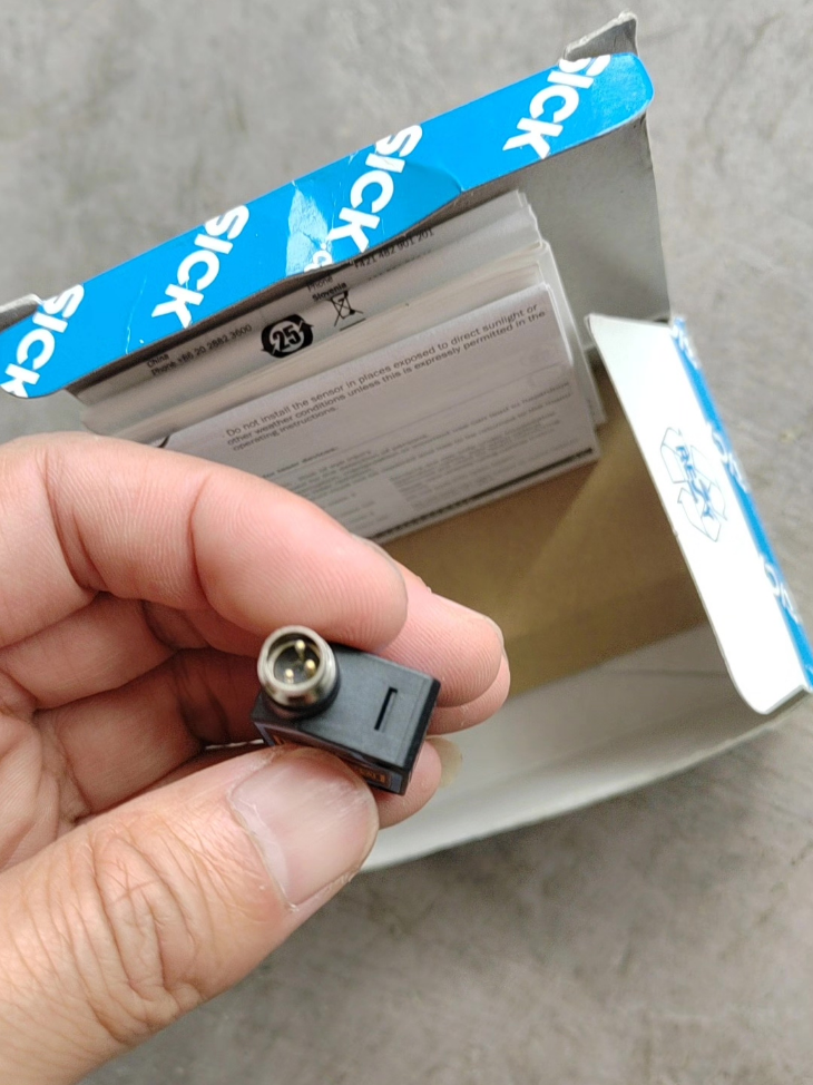

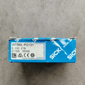
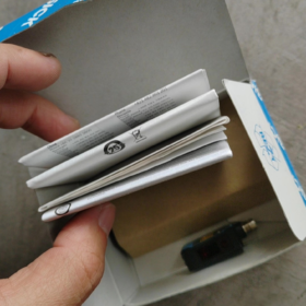
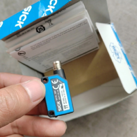
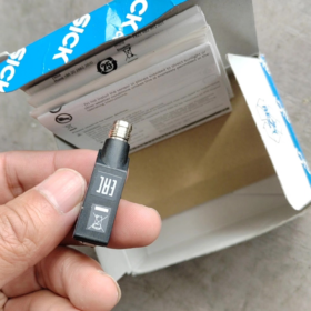
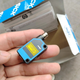
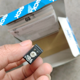
모델: WTB8L-P2131
시리즈: W8 Laser Miniature Laser Background Suppression Photoelectric Sensor
주문번호: 6033219
감지 원리: Diffuse reflection + Optical Background Suppression (BGS)
광원: 650 nm red laser, 레이저 클래스 1 (안전한, no eye injury risk)
산출: PNP, Light-on / Dark-on selectable via adjustment knob
커넥터: M8 3-pin male connector
표준 액세서리: 304 stainless steel mounting bracket BEF-W100-A
- Core Optical Specifications
| 매개변수 항목 | 사양 값 |
| 표준 감지 범위 (90% high-reflective white paper) | 30~300 mm |
| Stable Operating Range | 40~300 mm |
| 스팟 크기 (~에 300 mm) | Ø1.5 mm (ultra-fine laser spot for tiny object detection only) |
| 조정 방법 | 4-turn precision potentiometer |
| 응답 시간 | ≤0.25 ms |
| 맥스. 스위칭 주파수 | 2,000 헤르츠 (for high-speed production lines) |
- 전기 사양
- 공급 전압: DC 10~30 V, ripple ±10%
- 무부하 전류: 30 엄마
- 출력 부하: PNP, 최대. 100 엄마
- Signal Level: High ≈ Vs-1.8 V, Low ≈ 0 다섯
- 내장된 보호: 역극성 보호, 단락 보호, 과부하 보호
- 서비스 수명: Average LED service life of 100,000 hours at 25℃
- 기계 & 환경 사양
전체 치수: 11 mm (여) × 31 mm (시간) × 20 mm (디)
무게: 10 g
주택: ABS plastic; 렌즈: PMMA
유입 방지: IP67 (방진, protected against temporary immersion)
작동 온도: -10 ℃ ~ +50 ℃
저장 & 운송 온도: -40 ℃ ~ +70 ℃
설치: M3 threaded holes on housing, supplied with stainless steel bracket
MTTFd: 453 연령 (high-reliability industrial grade)
- 핀 할당 (M8 3-pin)
- 핀 1: DC 24V+ (Positive power supply)
- 핀2: PNP signal output
- 핀3: 0V GND (Negative power supply)
- 핵심 장점
- Ultra-fine laser spot Ø1.5 mm: Detects tiny components, thin labels, fine wires and miniature electronic parts. The standard LED version WTB8-P2131 has a 20 mm spot and cannot detect micro-parts.
- Powerful background suppression: Not disturbed by metal surfaces, conveyor belts or dark backgrounds; detection immune to object color.
- 2 kHz high-speed response: High-speed counting and presence detection for packaging, printing and electronics production lines.
- Miniature compact housing, easy installation in confined equipment spaces.
- IP67 dustproof and waterproof design, stable operation in workshop oily and dusty environments.
- 수업 1 원자 램프, no extra protective measures required, safe for internal machine installation.
- 일반적인 애플리케이션 시나리오
전자 산업: Presence detection of PCBs, tiny pins and SMD components
포장 산업: Detection of thin labels, medicine pellets, bottle caps and straws
3C Automation: Counting of miniature mobile phone parts and small plastic pieces
물류 운반: Identification of narrow-edge materials, fine wires and thin films
공작 기계 / 사출 성형: In-position detection of tiny ejector pins and small workpieces
- Series Distinction (WTB8L vs WTB8)
WTB8L-P2131: 레이저 광원, 1.5 mm 스팟, 2 kHz 스위칭 주파수, for micro-object detection
WTB8-P2131: Standard red LED, 20 mm 스팟, 1 kHz 스위칭 주파수, for regular large workpiece detection
- 선택 함정 회피
- When detecting black / low-reflective materials, reduce sensing distance and fine-tune potentiometer threshold;
- Do not stare directly into the laser beam for extended periods (수업 1 laser still requires standardized operation);
- Avoid long-term lens contact with cutting fluid and highly corrosive chemicals;
- Select shielded M8 3-core straight / elbow cables for sites with strong EMI from inverters.
Official Standard Installation Manual for 아픈 WTB8L-P2131
모델: WTB8L-P2131 | 주문번호: 6033219
시리즈: W8 Laser Miniature Laser Background Suppression Photoelectric Sensor
애플리케이션: High-precision detection of tiny objects within 30~300 mm
목차
- 안전 지침 (수업 1 원자 램프, 전기 안전)
- Unpacking Parts Verification
- Mechanical Mounting Specifications (Bracket Fixing, 토크, 장착 간격)
- Electrical Wiring Standards (M8 3-pin Assignment, 배선도)
- Optical Alignment & Potentiometer Calibration Procedures
- Indicator LED Status Description
- Environmental Mounting Limits & 일반적인 함정
- On-site Commissioning & Acceptance Procedure
- 문제 해결 매트릭스
- Maintenance Specifications
- 안전 지침 (Mandatory Compliance)
1.1 레이저 안전
광원: 650 nm red laser, 레이저 클래스 1, no eye hazard under normal operation;
Do not stare at the laser spot at close range for a long time; do not refract the beam with magnifiers or mirrors;
Cut off power supply before cleaning the lens during equipment maintenance.
1.2 전기 안전
Power must be disconnected before wiring, installing or removing cables;
Only DC 10~30 V power supply is allowed; AC220V input is strictly prohibited;
맥스. output load 100 엄마; cannot directly drive solenoid valves or contactors;
역극성 내장, short-circuit and overload protection, but standardized wiring is still required.
1.3 기계적 안전
ABS plastic housing; do not strike or squeeze the lens with excessive force;
Lens material PMMA; avoid soaking or wiping with alcohol and strong solvents.
- Standard Factory Supplied Parts List
| 목 | 사양 | 수량. |
| Sensor Main Unit | WTB8L-P2131 | 1 PC |
| Stainless Steel Mounting Bracket | BEF-W100-A (주문 번호. 5311520) | 1 PC |
| M3 Fixing Screws | Matching locking screws | 2 PC |
| Product Datasheet | Bilingual Chinese & English specification sheet | 1 복사 |
Optional Separately Ordered Parts: M8 3-core straight / elbow cables, extended mounting brackets, vibration-damping gaskets
- Mechanical Mounting Specifications
3.1 장착 치수
전체 사이즈: 11 mm (여) × 31 mm (시간) × 20 mm (디)
M3 internal threaded mounting holes on both sides of the housing
3.2 Bracket Mounting Steps
- Attach BEF-W100-A bracket to the sensor side, align M3 hole positions;
- Insert M3 screws and tighten in stages, single tightening torque ≤0.6 N·m;
- Fix the long slotted holes of the bracket to the machine frame for front/back and up/down fine adjustment;
- Pre-adjust all screws before final tightening to prevent laser spot offset caused by operational vibration.
3.3 Mandatory Mounting Distance Requirements
Minimum sensing distance: 30 mm; stable reliable range: 40~300 mm;
Recommended operating range: 50%~80% of rated distance (100~240 mm) for strongest anti-interference performance;
Clearance between target workpiece and background ≥10 mm to avoid false triggering;
Side-by-side multi-sensor installation: Center-to-center distance ≥40 mm to prevent mutual laser interference.
3.4 Mounting Angle Specifications
Laser optical axis must be perpendicular to the target material surface, tilt angle ≤±5°;
Excessive tilt causes spot deformation, sensing threshold drift and missed detection;
For fine wires and miniature parts, ensure the laser spot fully covers the workpiece center.
3.5 Environmental Mounting Prohibitions
No splashing cutting fluid or long-term dust accumulation in front of the lens;
Keep away from strong electromagnetic radiation zones of inverters and servo motors, distance ≥150 mm;
Do not install adjacent to high-temperature heat-generating components (max ambient temperature +50℃);
Install dust shielding plates for working conditions with continuous water mist or oil contamination.
- Electrical Wiring Standards
4.1 M8 3-pin Male Connector Pin Assignment (International Standard)
| 핀번호. | 와이어 색상 | 기능 | 배선 지침 |
| 핀 1 | 갈색 | DC24V+ | Positive power supply 10~30V DC |
| 핀2 | 검은색 | PNP signal output | Connect to PLC input / load positive terminal |
| 핀3 | 파란색 | 0V GND | Negative power supply & load negative terminal |
4.2 PNP Output Wiring Logic
- Connect one end of the load to Pin2 (black wire), the other end to 24V+;
- A pull-down resistor must be connected in series for PLC NPN-type inputs; PNP-compatible input modules are preferred;
- Use shielded M8 cables for high EMI sites, ground shield layer at single end to cabinet earth.
4.3 Electrical Limit Parameters
No-load current: 30 엄마; 맥스. 출력 전류: 100 엄마;
Ripple voltage ≤±10%; direct power supply from switching power supplies without filtering is forbidden;
Recommended cable length ≤10 m; use shielded cables for long wiring runs.
- Optical Alignment & Potentiometer Calibration (Core Mounting & 시운전 단계)
4-turn precision adjustable potentiometer on sensor top: Clockwise = increase sensing distance; Counterclockwise = reduce sensing distance.
Standard Calibration Procedure (BGS Background Suppression Mode)
- Power on and confirm the green stable indicator LED illuminates steadily;
- 단계 1: Place the target workpiece at actual detection position, align laser spot to workpiece center;
- Slowly rotate potentiometer clockwise until the orange output LED stays constantly lit;
- 단계 2: Remove workpiece, only keep background in position;
- Fine-tune potentiometer counterclockwise until the orange LED fully turns off;
- Repeat workpiece placement / removal test 3~5 times: LED ON with workpiece, LED OFF without workpiece, no flickering = calibration completed;
- Lock the potentiometer dust cap after calibration to prevent offset from vibration.
Calibration Tips for Special Materials
Black low-reflective workpieces: Shorten sensing distance to ≤200 mm and slightly raise threshold;
Transparent films / thin sheets: Reduce sensing distance and avoid spot hitting reflective edges;
고속 생산 라인: Ensure green LED stays steady (안정적인 신호) without flickering after calibration.
- Dual Indicator LED Status Description
Green LED (Stability Indicator)
계속 켜져 있음: Sufficient signal, 안정된 검출;
섬광: Marginal signal, excessive distance / insufficient object reflectivity, prone to false detection;
끄다: No valid reflection, out of sensing range.
Orange LED (Switch Output Indicator)
계속 켜져 있음: Object detected, PNP output conductive;
끄다: No object detected, output disconnected;
Rapid flashing: 단락 / overload protection activated; cut off power immediately to inspect wiring.
- Environmental Mounting Parameter Limits
| 목 | Allowable Range | Consequence of Exceeding Limits |
| 작동 온도 | -10℃~+50℃ | Thermal drift at high temp, no response at low temp |
| 저장 & 운송 온도 | -40℃~+70℃ | Aging of electronic components |
| Ingress Protection Grade | IP67 | Prohibit long-term immersion or direct high-pressure water jet spraying on lens |
| 습기 | 5%~95% non-condensing | Condensation causes lens reflection and false triggering |
| 진동 저항 | 10~2000 Hz, 100 m/s² | Spot offset and loose screws beyond rated range |
- Complete Machine On-site Acceptance & Verification Procedure
- 기계적 검증: 느슨한 괄호 없음, laser spot stably positioned on material detection surface;
- Electrical Verification: Supply voltage 22~26V DC without voltage drop; load current <100 mA;
- Functional Verification:
Reliable triggering of workpieces within rated range;
Complete background suppression with zero false triggering;
500 consecutive reciprocating operations without missed or false detection;
- Stability Verification: Run equipment at full load for 30 minutes with no abnormal LED flickering.
- 문제 해결 매트릭스 (Common Post-installation Issues)
| 결함 증상 | 근본 원인 | Mounting Correction Measures |
| Orange LED fails to light when workpiece is present | 1. Distance out of range; 2. Potentiometer threshold too low; 3. Laser spot misaligned with workpiece | Shorten mounting distance, turn potentiometer clockwise, realign laser spot |
| Orange LED stays ON without workpiece (background false triggering) | Excessively reflective background, workpiece-to-background gap too small, over-high threshold | Reduce sensing distance counterclockwise, reserve ≥10 mm gap between workpiece and background |
| Green LED flashes continuously, unstable detection | Excessive distance, lens covered by dust, severe voltage fluctuation, loose mounting from vibration | Shorten sensing distance, clean lens, add power supply filtering, retighten bracket screws |
| Orange LED flashes rapidly | Output short-circuit, load current exceeds 100 엄마, reversed power wiring | Cut off power to inspect cables, replace smaller load, correct brown/blue power wiring |
| All LEDs off, sensor completely non-functional | Power circuit break, M8 connector not fully tightened, supply voltage below 10V | Re-seat M8 connector, measure supply voltage, replace cables |
- Long-term Maintenance Specifications
- 일일점검: Lens free of oil and dust accumulation, brackets tight without looseness;
- Weekly Cleaning: Wipe lens with dust-free soft cloth dampened with clean water; acetone and banana oil are prohibited;
- Monthly Recheck: Recalibrate potentiometer threshold and verify stable LED status;
- Annual Inspection: Check cable aging and integrity of M8 connector waterproof sealing rings.
- Forbidden Mounting Operations (엄격한 제한)
- Do not tighten screws with torque exceeding 0.6 N·m to avoid cracking housing threads;
- Do not aim lens at highly reflective metal surfaces for prolonged direct irradiation;
- Do not sharply bend cables with bending radius <5 mm;
- Do not install directly without protective measures in condensing or continuous water mist environments;
- Do not connect high-power solenoid valves or cylinder coils in parallel to output terminals;
- Do not install multiple WTB8L laser sensors facing each other at close range.










NH42-63-318x560.png "CHINT PC형 자동절환스위치 (ATS)NH42-63/4SZ")



