 Contactor,circuit breaker,sensor,Encoder,PLC,Converter

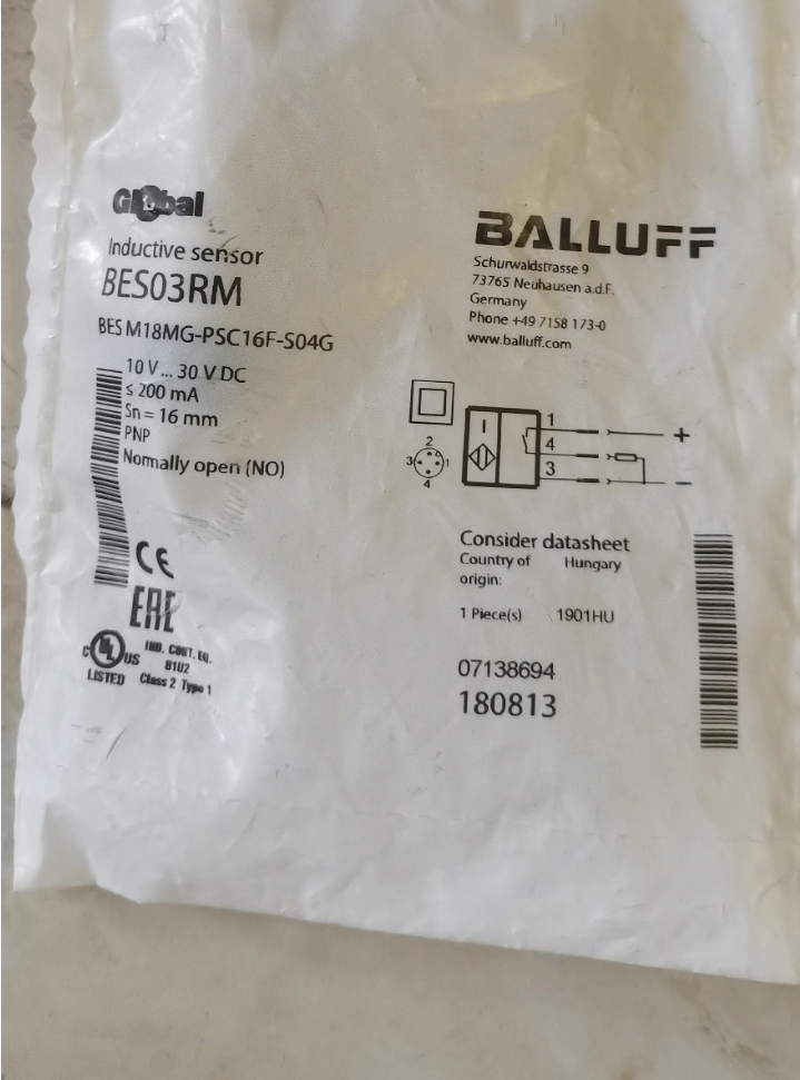

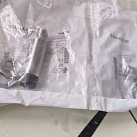
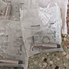
Order No.: BES03RM; Full Model: BES M18MG-PSC16F-S04G, M18-thread non-flush mount inductive proximity sensor.
Model Code Explanation
M18: M18×1 cylindrical threaded housing
MG: Non-flush mounting, extended sensing range
P: PNP output
SC: 3-wire DC
16F: Nominal sensing distance 16 mm
S04G: M12-A-coded male connector, 3-pin
Core Electrical & Mechanical Specifications
| Item | Specification |
| Sensing Distance | 16 mm (non‑flush) |
| Output | PNP‑NO Normally Open |
| Supply Voltage | 10‑30 VDC |
| Max. Load Current | 200 mA |
| Switching Frequency | 430 Hz |
| Ingress Protection | IP68 |
| Operating Temperature | -40 … +85 ℃ |
| Housing | Nickel‑plated brass; Sensing face: PBT plastic |
| Dimensions | M18×1, overall length 66 mm |
| Connection | M12‑3‑pin male plug |
| Protections | Reverse‑polarity protection, short‑circuit protection, overload protection |
| Weight | 52 g |
| HS Code | 85365019 |
M12-3-pin Pin Assignment (Male Connector)
- Brown: DC + (10-30V)
- —— (Not connected)
- Blue: 0V/GND
- Black: Signal output (PNP)
Note: This is a 3-pin M12, not standard 4-pin. Select M12-A-coded 3-core cable for procurement.
Installation Guidelines
- Non-flush type. Do not sink fully into metal bracket; sensor front face must protrude from metal surface.
- Center-to-center distance between adjacent sensors ≥36 mm to prevent mutual interference.
- LED is located at plug root, 360° visible; LED lights up upon target detection.
Common Replacement Options
Original Balluff Equivalent
BES M18MG-NSC16F-S04G (BES03RN): Same dimension & sensing range, NPN normally-open version.
Domestic Compatible Alternatives (M18 non-flush,16 mm,PNP-NO,M12 connector)
Inovance: IS-M18-16PO-M12
Hugong: LJ18A3-16-Z/BY-G (M12 connector variant)
Replacement checkpoints: confirm 16 mm sensing distance, non-flush mount, PNP-NO, M12-3-pin, 10-30VDC supply.
Typical Applications
Metal-part detection on assembly lines, machine-tool limit sensing, conveyor position confirmation, warehousing & logistics, harsh-environment use (low temperature, dust, water splash).
Balluff BES03RM (BES M18MG-PSC16F-S04G) Complete Installation Manual
Order No.: BES03RM, Full Model: BES M18MG-PSC16F-S04G, M18 non-flush inductive proximity sensor
- Product Overview
- Type: Inductive proximity switch, non-flush (cannot be flush-mounted)
- Housing: M18×1 nickel-plated brass; sensing face PBT engineering plastic
- Sensing distance: Nominal Sn=16 mm, effective operating distance Sr≈16 mm
- Output: PNP NO normally-open, 3-wire DC 10-30VDC, max. load 200 mA
- Interface: M12-A-coded 3-pin male plug (NOT 4-pin)
- Rating: IP68; Operating temperature -40℃~+85℃; Switching frequency 430 Hz
- Standard accessories: 2 pcs M18 lock nuts
- Mechanical Installation Specifications (Critical: Never sink non-flush sensor into metal bore)
⚠️This is a non-flush sensor. The sensing face must not sink inside metal mounting holes. Sinking will cause severe sensing-range loss, false triggering or failure to detect targets.
2.1 Dimensions (Unit: mm)
Thread: M18×1
Overall length: 66 mm
Status LED at M12 plug root, 360° viewable; LED illuminates when metal target is detected
Lock nut across-flats: 24 mm
2.2 Mounting Torque
Lock-nut tightening torque: 15-20 N·m, maximum 25 N·m. Exceeding will cause thread stripping or housing cracking.
2.3 Multi-sensor Spacing
Center-to-center distance between identical sensors ≥36 mm to avoid crosstalk false switching
Minimum clearance between sensor sidewall and nearby metal wall ≥18 mm; metal must not hug sensor body
Reference target: 18×18 mm steel plate; smaller actual targets reduce effective sensing range.
2.4 Working Gap to Target
Recommended operating gap: 4-12 mm; maximum reliable operating gap ≤14 mm; avoid continuous operation at the 16 mm limit threshold.
Sensing face shall face metal target as perpendicular as possible; tilt angle preferably <15°. Larger tilt reduces effective sensing distance.
- Electrical Wiring (M12-A-coded 3-pin male pin-out)
| M12 Pin No. | Wire Color | Function |
| 1 | Brown | DC+ Power 10‑30V DC |
| 2 | — | Not connected, no internal wiring |
| 3 | Blue | 0V / GND |
| 4 | Black | PNP signal output (NO Normally Open) |
❗Use M12-A-coded 3-core female-end cables. Standard 4-core M12 cables are also acceptable, leave pin 2 unconnected.
Built-in Electrical Protections
Reverse-polarity protection, output short-circuit protection, overload protection.
PLC connection: Connect to PNP-type digital input module.
Inductive loads (relay coils): Fit free-wheeling diode in reverse parallel across coil terminals.
Resistive loads: Keep load current ≤200 mA.
Prohibited Operations
- Do NOT apply AC voltage; only 10-30 VDC DC supply permitted.
- Route sensor cables separately from high-power power cables to minimize electromagnetic interference.
- Power-on Commissioning Procedure
- Complete all wiring; verify no short-circuits before applying power.
- No metal target present: LED OFF.
- Move steel target toward sensing face: LED turns ON within sensing range; LED turns OFF after removing target.
- Cycle target repeatedly: confirm stable ON/OFF without flickering.
This sensor has no sensitivity potentiometer. Sensing distance cannot be adjusted electronically; adjust mechanical gap only.
- Environmental Operating Conditions
- IP68 rating permits temporary water immersion; fully tighten M12 connector, poor sealing degrades IP rating.
- Operating temperature -40℃~+85℃; select low-temperature-rated cables for cold environments.
- Avoid heavy impact to PBT sensing face; prevent welding-spatter exposure.
- Troubleshooting
| Symptom | Check Items |
| LED never lights | Check 10‑30VDC supply, brown/blue wiring, fully‑seated M12 plug |
| LED always ON without target | 1. Sensor sunken into metal bore (most common fault); 2. Nearby metal too close to sensor body; 3. Insufficient inter‑sensor spacing; 4. Output short‑circuit |
| Intermittent flickering when target arrives | Operating gap near 16 mm limit; nearby metal interference; EMI from power cables; undersized target |
| LED OFF even with target present | Wiring error; excessive target gap; non‑ferrous target (Al/Cu reduce sensing performance) |
- Official Documentation Access
Search order number BES03RM on Balluff official website. Enter product page, download original datasheet and 2D/3D CAD files under Downloads tab.
Generic installation document ID for extended-range inductive sensors: 939229.
- Spare & Replacement References
- NPN counterpart: BES03RN (BES M18MG-NSC16F-S04G)
- Domestic compatible: M18 non-flush,16 mm,PNP-NO,M12-3-pin connector.
Balluff BES03RM (BES M18MG-PSC16F-S04G) Full Technical Datasheet
Order No.: BES03RM; Full Model: BES M18MG-PSC16F-S04G
Type: M18 cylindrical non-flush-mount inductive proximity sensor
Basic Information
| Item | Specification |
| Operating Principle | Inductive, detects metallic targets |
| Mounting Style | Non‑flush, cannot be flush‑mounted into metal bore |
| Housing | M18×1 external thread, nickel‑plated brass |
| Sensing‑face Material | PBT engineering plastic |
| Overall Dimensions | Φ18 mm × total length 66 mm |
| Lock‑nut across‑flats | 24 mm, 2 lock‑nuts supplied |
| Weight | 52 g |
| HS Code | 85365019 |
| Approvals | CE, UKCA, cULus, WEEE, compliant with IEC 60947‑5‑2 |
Sensing Performance
| Item | Specification |
| Nominal Sensing Distance Sn | 16 mm |
| Effective Operating Distance Sr | 12.8 ~ 19.2 mm |
| Reference Target | 18 mm×18 mm×1 mm steel plate |
| Switching Frequency | 430 Hz |
| Hysteresis | ≤10% of Sn |
| Sensitivity Adjustment | Not adjustable (fixed range) |
Electrical Ratings
| Item | Specification |
| Supply Voltage Ub | 10 ~ 30 VDC |
| No‑load Current | ≤8 mA |
| Output Type | PNP Normally‑Open (NO), 3‑wire DC |
| Max. Load Current | 200 mA |
| Built‑in Protections | Reverse‑polarity, short‑circuit, overload protection |
| Status Indicator | LED at M12 plug root, 360° visible; lights when metal detected |
| Interface | M12‑A‑coded 3‑pin male plug (NOT 4‑pin) |
M12-3-pin Pin-out
| Pin No. | Wire Color | Function |
| 1 | Brown | DC+ Power 10‑30VDC |
| 2 | — | Not connected |
| 3 | Blue | 0V / GND |
| 4 | Black | PNP signal output NO Normally‑Open |
Cable recommendation: M12-A-coded female-end, 3-core cable. 4-core cable usable with pin 2 left open.
Mechanical & Environmental Ratings
| Item | Specification |
| Ingress Protection | IP68 (connector fully tightened) |
| Operating Temperature | ‑40 ℃ ~ +85 ℃ |
| Recommended Lock‑nut Torque | 15‑20 N·m; absolute maximum 25 N·m to avoid thread damage |
| Vibration Resistance | 10‑55 Hz, amplitude 1 mm, IEC 60068‑2‑6 |
| Shock Resistance | 30 g / 11 ms, IEC 60068‑2‑27 |
Installation Spacing Rules
- Adjacent identical-model sensors: center-to-center ≥36 mm for anti-crosstalk.
- Minimum gap between sensor side and metal wall: ≥18 mm.
- Suggested working gap: 4-12 mm; avoid continuous operation near 14-16 mm threshold.
- Keep target perpendicular to sensing-face; tilt angle<15°, sensing distance drops with larger tilt.
Related Original-part Numbers
- BES03RN (BES M18MG-NSC16F-S04G): same mechanical & range, NPN normally-open.
Important Notes
- Non-flush-type sensor: sensing face must protrude from metal mounting surface. Sinking causes range degradation, false-switching or no detection.
- DC-only device, AC input forbidden.
- Fit reverse-parallel free-wheeling diode for inductive loads e.g. relay coils.
- Separate sensor signal cables from high-power power cables to reduce EMI.
Quick Troubleshooting Summary
LED permanently ON without target: Likely sunken installation, nearby metal interference or insufficient inter-sensor distance.
Flickering upon detection: Working gap close to 16 mm maximum limit; reduce mechanical gap.
LED never illuminates: Verify supply voltage, M12 connector seating and brown-blue power wiring.





NH42-63-318x560.png "CHINT PC-type automatic transfer switches (ATS)NH42-63/4SZ")



