 Contactor,circuit breaker,sensor,Encoder,PLC,Converter

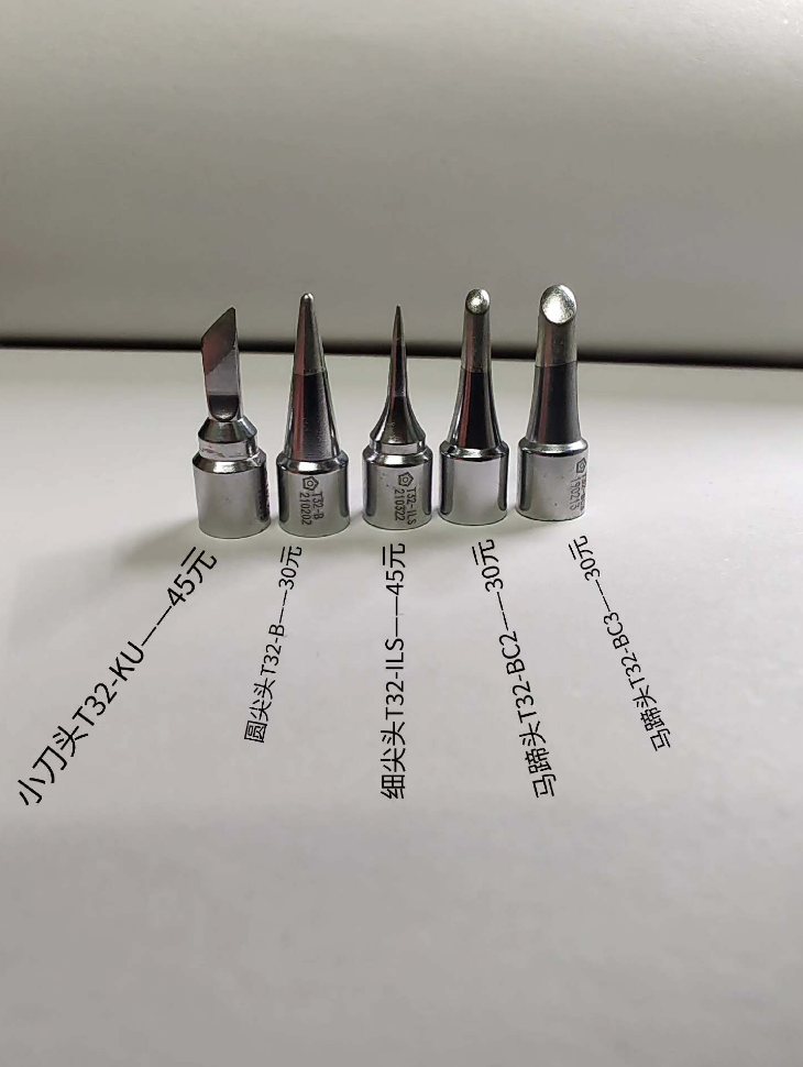

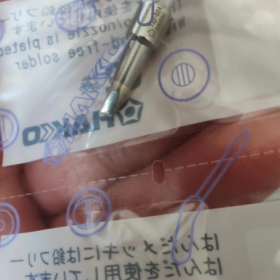
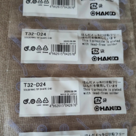
Basic Model Information
Brand: HAKKO (Japanese soldering station brand; official spelling is HAKKO)
Series: T32 Soldering Tip Series
Compatible Soldering Iron Handle: FX-8901 (Matched with FX890 main unit, 90W power)
Model Breakdown
T32: Series code, designed for high-power FX890 soldering station
D: Chisel / flat screwdriver tip (D-series = flat chisel-shaped tips)
24: Blade width of 2.4 mm
- Core Dimension Parameters
- Blade Shape: Straight flat chisel (Type D)
- Blade Width: 2.4 mm
- Blade Thickness: Approx. 0.6 mm
- Overall Length: Standard universal length for all T32 tips, compatible with FX8901 heating core
- Plating: Lead-free dedicated iron plating, corrosion-resistant and enables uniform solder melting
- Application Scenarios
- SMD Component Soldering: 0805/1206 resistors & capacitors, pins of small SOP ICs
- Wire Soldering: Fine wires, ribbon cables, wire harness terminal tinning
- PCB Rework & Touch-Up: Medium-sized pads, balances heat transfer and operation precision
- Not Suitable For: Tiny 0402 components (T32-D08/D12 recommended), large ground pads (wider tips D32/D52 recommended)
- Selection Comparison Chart of All D-Type Chisel Tips in T32 Series
| Model | Blade Width | Application Working Conditions |
| T32-D08 | 0.8mm | Micro SMD components, fine-pin IC leads |
| T32-D12 | 1.2mm | 0402 / 0605 chip components |
| T32-D16 | 1.6mm | General SMD components |
| T32-D24 | 2.4mm | General SMD parts, wire harness soldering |
| T32-D32 | 3.2mm | Large solder pads, thick wires |
| T32-D52 | 5.2mm | Large ground copper areas, multi-pin connectors |
- Matching & Operation Guidelines
- Only compatible with FX890 Main Unit + FX8901 Handle, cannot be interchanged with FX888D / T12 series soldering tips
- Operating Temperature Range: 300~450℃; recommended 360~400℃ for lead-free solder
- Maintenance: Clean with damp sponge regularly to avoid dry burning and oxidation; severely oxidized tips need re-tinning after surface conditioning
- Original Part Number: B5317 (Quote this code for procurement)
- Easy Brand Distinction
HAKKO: German brand for floor cleaning equipment
HAKKO: Japanese brand for soldering equipment; T32-D24 belongs exclusively to Hakko welding consumables, unrelated to cleaning machinery
Full Comparison: HAKKO T32-D12 vs T32-D24
(Universal T32 chisel tips for FX890 / FX888DX soldering stations)
- Basic Parameter Comparison Table
| Comparison Item | T32-D12 | T32-D24 |
| Blade Width | 1.2mm | 2.4mm |
| Blade Thickness | 0.7mm | 0.5mm |
| Compatible Soldering Stations | FX890 (FX8901 Handle), FX888DX (FX8806 Handle) | Same as left; all T32 tips are directly interchangeable |
| Outline Structure | Narrow thin chisel, small contact surface | Wide flat chisel, double heat transfer contact area |
| Heat Storage Capacity | Low, slow heat recovery, for micro solder joints | High heat retention, fast thermal conduction, stable temperature during continuous soldering |
| Solder Carrying Area | Narrow, holds minimal solder | Wide flat surface, holds large volume of solder |
- Detailed Core Differences
2.1 Dimension & Heat Transfer Efficiency (Most Critical Difference)
T32-D12 (1.2mm Narrow Tip)
Narrow blade with thicker wall creates small overall contact area. It delivers less heat at equal temperature, heats solder points slowly, and temperature drops easily during continuous soldering.
T32-D24 (2.4mm Wide Tip)
Double blade width and flat surface greatly boost heat conduction efficiency. It fully unlocks the performance of the 90W FX890 station, maintaining steady temperature for mass continuous soldering.
2.2 Differentiated Application Scenarios
T32-D12 (Dedicated to Precision Micro Soldering)
- Micro SMD: 0402 / 0605 resistors, capacitors, micro LEDs
- Fine-pin ICs: Low-pitch SOP, mini SOIC, fine pins of ribbon cables
- High-density compact PCBs; prevents solder bridging and thermal damage to adjacent tiny components
- Precision rework for mobile phones, Bluetooth earbuds, miniature sensors
T32-D24 (General Mass Soldering & Medium-Large Joints)
- Standard SMD: 0805/1206 components, drag soldering for regular SOP connector pins
- Wire harness, stranded wire and terminal tinning; holds enough solder in one pass
- Power supply pads, medium ground copper areas, electrolytic capacitor leads
- Mass through-hole soldering and drag soldering for multi-pin pin headers, greatly boosting working efficiency
- Operation Feel & Limitations
T32-D12: High precision, but low solder capacity. Repeated solder feeding required for thick wires/large pads, low efficiency, prone to cold solder joints on large thermal masses.
T32-D24: High fault tolerance, smooth drag soldering. Drawback: risk of accidental short-circuit or thermal damage to neighboring tiny components in ultra-dense PCB layouts.
2.4 Recommended Temperature Settings (Lead-free Sn-Ag-Cu Solder)
T32-D12: 380~410℃ (Small contact area requires higher temperature to compensate insufficient heat transfer)
T32-D24: 360~390℃ (Ample heat conduction eliminates the need for extreme high temperature, slowing tip oxidation)
- Quick Selection Guide
- Soldering micro chips, low-pitch ICs, high-density mini PCBs → Choose T32-D12
- Soldering standard SMD, wire terminals, mass through-hole parts, power pads → Choose T32-D24
- Balanced precision & general work: Prepare both tips. Use D24 as daily main tip, switch to D12 for precision rework.
- Shared Identical Features
- Identical mounting size and overall length, direct interchange without replacing heating core/handle
- Same material, lead-free iron plating and oxidation resistance grade
- Same working temperature range limit (50–480℃)
- Identical maintenance rules: Clean with damp sponge, prohibit dry burning, re-tin after oxidation repair
Complete Practical Operation Tutorials for HAKKO T32-D12 / T32-D24
Compatible Stations: FX890 (90W high-power), FX888DX. Two tips share the same mounting interface; only soldering techniques, temperature control and applicable scenes differ.
- Universal Basic Tutorials (For Both Tips: New Tip Tinning, Daily Maintenance, Standard Soldering Specs)
1.1 First Activation Tutorial for Brand-New Tips (Mandatory, Avoid Permanent Oxidation & Non-wettable Surface)
- Power on the station, preheat to 320℃, wait until the tip reaches full temperature
- Soak cleaning sponge and squeeze dry (no dripping water), wipe off anti-rust oil on the tip
- Coat the entire blade evenly with rosin-core solder wire (0.6/0.8mm), fully covering the iron plating
- Hold for 10 seconds, lightly wipe with sponge, reapply a thin protective tin layer. Only raise temperature for soldering after completion.
> Warning: Dry burning at high temperature without pre-tinning will cause permanent black oxidation that cannot hold solder.
1.2 General Maintenance Guide (Triple Tip Service Life)
- Between soldering cycles: Wipe flux/solder residue every 3~5 joints, immediately reapply a thin tin film to isolate air
- Shutdown procedure: Cool down to 280℃, clean and re-tin the tip before powering off. Never cut power under high temperature.
- Temperature Limit Rule: Max 410℃ for lead-free solder; oxidation rate doubles above 470℃.
- Oxidation Repair Steps
① Mild blackening: Wipe with sponge + liquid flux, re-tin the surface
② Severe oxidation: Dip tip in tip revitalizer for 5 seconds, wipe and re-plate solder. File grinding is forbidden as it damages the protective iron plating.
- Prohibited Operations: Pry PCB boards / scrape pads with the tip, prolonged idle high-temperature burning, sudden cooling by soaking hot tip in waterlogged sponge.
1.3 Standard 5-Step Soldering Process (Applicable to Both Tips)
- Heat: Place tip blade at 45°, touching both solder pad and component pin simultaneously (1~2s)
- Feed Solder: Touch solder wire to the junction of pad and pin, do not feed solder directly onto the tip
- Wetting: Let solder fully cover the pad to form a smooth volcano-shaped joint (2~3s)
- Retract Solder Wire first
- Lift soldering iron diagonally upward along the pin, keep components stationary until natural cooling
> Qualified Joint Standard: Bright luster, complete solder climb, no burrs, no cold joints, no solder bridging.
- Exclusive Practical Tutorial for T32-D12 (1.2mm Narrow Chisel Tip)
Target Scenarios: 0402/0605 micro SMD, low-pitch SOP ICs, precision rework for Bluetooth earbuds/micro sensors, high-density mini PCBs
2.1 Standard Temperature Parameters (Lead-free Sn-Ag-Cu)
General precision soldering: 380~410℃
Tiny 0402 chips: Cap at 390℃, single joint heating ≤ 2 seconds to prevent component detachment
2.2 Special Soldering Techniques
(1) Soldering Tutorial for 0402/0605 Resistors & Capacitors
- Pre-tin a small amount of solder on one PCB pad
- Hold the chip component with tweezers and align with pads; press the pre-tinned pad lightly with the narrow D12 blade to melt solder and fix the component
- Heat the opposite pad with the blade edge, feed tiny amount of solder for full wetting
- Inspect after cooling. Small contact surface avoids accidental bridging to adjacent pads.
(2) Drag Soldering for Low-Pitch IC Pins (Pitch ≤0.8mm)
- Fix IC with two diagonal tack points, coat thin liquid flux on all pins
- Use the side edge of D12 blade to lightly contact pins, avoid full-surface compression to limit solder load
- Tilt PCB at 30°, drag tip at constant slow speed; excess solder adheres to narrow blade for removal
- If bridging occurs: Reapply flux and drag gently again, or clean with desoldering braid
> Core Advantage: Narrow blade minimizes accidental contact with surrounding micro devices, ideal for dense circuit boards.
2.3 D12 Operation Pitfalls to Avoid
- Not suitable for thick wires / large power pads: Low heat storage and slow heat recovery easily cause cold solder joints & poor bonding
- Do not apply heavy pressure on blade: Thin narrow metal deforms easily and loses protective plating
- Take intermittent cooling breaks during mass soldering; raise temperature by 10~20℃ if constant temperature drop occurs
- Exclusive Practical Tutorial for T32-D24 (2.4mm Wide Flat Chisel Tip)
Target Scenarios: 0805/1206 SMD, stranded wires, pin header connectors, power pads, ground copper planes, mass drag soldering
3.1 Standard Temperature Parameters (Lead-free Sn-Ag-Cu)
General SMD / ribbon cable soldering: 360~390℃
Large ground copper areas: 390~400℃ (Wide blade delivers sufficient heat without extreme temperature)
3.2 Core D24 Operation Tutorial (Primary General-Purpose Tip)
(1) Tinning & Soldering Wire Harness Terminals
- Dip stripped wire ends in rosin; load ample solder on flat D24 blade to tin wire evenly in one pass
- Fit flat blade against both PCB pad and pre-tinned wire for fast heat transfer over large contact area
- Retract iron once solder fully encapsulates wire and pad for robust, low-resistance joints.
(2) Mass Drag Soldering for Multi-Pin Headers & SOP ICs (High Efficiency Core Skill)
- Secure IC and coat flux on all pins
- Spread a thin layer of solder evenly across flat D24 blade as heat transfer medium
- Tilt PCB at 40°, press flat blade against full row of pins and drag at uniform speed
- Wide contact surface heats all pins synchronously, one-step forming reduces repeated heating damage to PCB substrates.
(3) Soldering Power Pads & Ground Copper Planes
Large copper planes dissipate heat rapidly and cannot be fully soldered with narrow D12 tips. D24 dedicated workflow:
- Set temperature to 390℃, fully attach blade to copper plane for 2 seconds preheating
- Apply sufficient solder and flux; continuous heat from wide contact surface eliminates cold joints and incomplete wetting.
3.3 D24 Operation Pitfalls to Avoid
- Use cautiously on ultra-dense compact boards: Wide blade easily creates solder bridges and short-circuits nearby micro components
- Control solder volume during drag soldering; excess solder on blade causes bridging. Clean tip every 3 pins dragged.
- Lower temperature to 360℃ and shorten heating duration when soldering micro LEDs or thermally sensitive components.
- Mixed Tip Switch Workflow for Workshop High Efficiency
- Mass general soldering (ribbon cables, 0805 chips, pin headers, power pads): Main working tip = D24 for maximum efficiency
- Intermittent precision rework (0402 chips, low-pitch ICs, dense mini PCBs): Switch to D12
- Tip Replacement Steps
① Cool soldering station down to 300℃
② Remove old tip, clean residual solder slag inside heating core cavity
③ Install new tip, raise temperature to 320℃ for initial protective tinning, then adjust to working temperature
- Recommended Matching Consumables: 0.6mm solder wire for D12; 0.8mm solder wire for D24 for precise solder volume control
Authorized Hakko Official Tutorials (Authoritative Standard Techniques)
Search Keywords:
HAKKO T32 series soldering tip maintenance
FX890 T32-D12 fine pitch soldering
FX890 T32-D24 cable & pad soldering
Official Website Section: Hakko Japan official consumable maintenance zone (contains graphic & video guides for tip tinning and maintenance)
Bilibili Search Keywords:
Hakko FX890 T32-D12 0402 chip soldering tutorial
Full drag soldering process for SOP IC with T32-D24 tip
Complete oxidation repair & maintenance guide for T32 soldering tips
Douyin Search Keywords:
90W Hakko soldering station narrow vs wide tip soldering comparison
Precision rework with D12, mass soldering with D24 practical demonstration
Professional Electronic Engineering Text Tutorials (CSDN / Electronic Fan Forum)
- 《SMT Manual Drag Soldering Tip Selection & Practical Comparison: D12 vs D24》
- 《Temperature Control & Operation Specifications for T32 Full Series Tips on FX890 High-Power Soldering Station》
- 《Anti-Short Circuit Operation Skills for Micro Component Soldering with Narrow Chisel Tips》





NH42-63-318x560.png "CHINT PC-type automatic transfer switches (ATS)NH42-63/4SZ")



