 Contactor,circuit breaker,sensor,Encoder,PLC,Converter

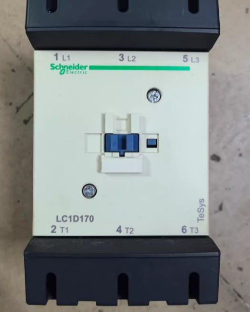


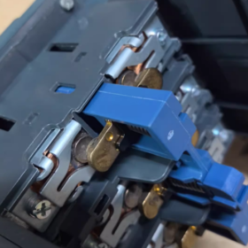
- Complete Model Code Breakdown (Standard Order Code: LC1D170XXC)
- LC1D: Standard AC Contactor of TeSys D Series
- 170: Rated operational current of 170A under AC-3 load at 440V
- 00: No built-in auxiliary contacts on main body (models ≤95A come with 1NO+1NC; auxiliary modules must be fitted for models ≥115A)
- XX: Coil voltage code (7 = universal for 50/60Hz)
B7: AC24V; F7: AC110V; M7: AC220V; Q7: AC380V; V7: AC400V
BD: DC24V DC coil
- C: Manufactured in Tianjin, China; imported versions have no suffix C
Common Complete Models
LC1D170M7C: AC220V coil (most widely used)
LC1D170F7C: AC110V coil
LC1D170Q7C: AC380V coil
- Core Electrical Parameters
Main Circuit Current & Power (AC-3 Motor Load, 440V)
AC-3 operational current Ie: 170A; conventional thermal current Ith = 200A
Matched motor power:
380V: 90kW; 415V: 100kW; 660V: 110kW
Rated insulation voltage Ui = 1000V; impulse withstand voltage 8kV
Short-time withstand capacity: 1400A for 1 second, 1200A for 10 seconds
Service Life & Operating Frequency
Mechanical life: 8 million operations
AC-3 electrical life: 800,000 operations (440V)
Max operating frequency: 1,200 operations per hour
Environmental Specifications
Operating temperature: -5℃ ~ +60℃; storage temperature: -40℃ ~ +70℃
Maximum applicable altitude: 3,000m (derating required above 1,000m)
Protection class: IP2X finger-safe; TH anti-corrosion treatment for humid & hot environments
Compliance standards: IEC60947-4-1, GB14048.4; CCC / UL / CE certifications
Overall Installation Dimensions (Width × Height × Depth)
120mm × 158mm × 136mm; standard vertical DIN rail mounting
- Coil Characteristics
Allowable voltage fluctuation: 70%~120% of rated coil voltage for stable pull-in across wide voltage range
Pull-in time: 20~35ms; breaking time: 40~75ms
Universal coil for 50/60Hz, global applicability
- Extension Accessories (Must Be Ordered Separately)
- Auxiliary Contact Modules
Top mounting: LADN series (LADN11 = 1NO + 1NC; LADN22 = 2NO + 2NC)
Side mounting: LADN side modules without increasing overall height
- Time Delay Modules: LADT on-delay, LADR off-delay
- Mechanical Interlock: LAD9R1 for forward/reverse reversible circuits
- Thermal Overload Relay: Matched LR9D63 (adjustment range: 80~180A)
- Arc Extinguishing & Wiring Accessories: Main circuit protective cover, busbar terminals
- Typical Application Scenarios
- Start/stop control for 90kW high-power fans, water pumps and air compressors
- Heating circuits of central chiller units and industrial ovens
- Star-delta starters and forward/reverse reversible control cabinets
- Power factor correction capacitor cabinets, large conveying equipment
- Model Selection & Replacement Instructions
Upgrading Replacement Within Same Series
LC1D170 upgrade model: LC1D170M7C, direct replacement with identical specifications; LC1G180 of TeSys G series as capacity expansion alternative
Model Selection Pitfalls to Avoid
- No built-in auxiliary contacts on main unit; LADN auxiliary modules are mandatory for automatic control circuits
- Derate by 10%~20% when ambient temperature exceeds 40℃ or altitude above 1,000m
- Do not select directly based on 170A rating for capacitive loads (AC-6b); upgrade one size higher
- Vertical mounting only; horizontal installation aggravates contact bounce and ablation
- Wiring Key Points
Main circuit: L1/L2/L3 as incoming terminals on upper side; T1/T2/T3 as load terminals on lower side
Coil terminals: A1, A2; wrong voltage connection will burn out the coil
Main circuit supports thick cable / busbar wiring; detachable insulating cover facilitates wiring
Complete Working Principle of Schneider LC1D170 AC Contactor
LC1D170 is an electromagnetic AC contactor that opens and closes main contacts via electromagnetic attraction. It consists of three coordinated core assemblies: coil electromagnetic system, main contact arc extinguishing system, and spring reset mechanism.
- Three Internal Core Assemblies
- Electromagnetic Driving Mechanism (Coil + Fixed Core + Moving Core)
Coil: Control voltage (AC220V/380V etc.) connected to terminals A1 and A2
Fixed core: Fixed on base with embedded short-circuit ring
Moving core: Rigidly linked with moving main contacts and equipped with reset spring
- Main Contacts & Arc Extinguishing Chamber
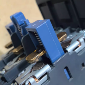
Three pairs of high-current main contacts (L1-T1, L2-T2, L3-T3) fitted with metal grid arc shield; rated for 170A motor main circuit current carrying capacity
- Reset Spring & Auxiliary Contact Base
The spring pulls the moving core apart to open contacts upon power cut-off. No built-in auxiliary contacts on this model; LADN modules must be fitted to implement self-locking and interlock logic.
- Full Pull-in Process When Coil Energized (Contactor Closed)
- Alternating Magnetic Field Generated by Energized Coil
Control circuit closes, rated AC voltage supplied to A1/A2, and alternating magnetic flux passes through fixed and moving cores.
- Short-circuit Ring Eliminates Vibration Noise
AC voltage crosses zero 100 times per second, causing instantaneous magnetic field loss and core chattering. A copper short-circuit ring embedded on fixed core end face generates lag magnetic field via eddy current, maintaining stable attraction at zero-cross points for silent steady pull-in.
- Electromagnetic Attraction Overcomes Spring Resistance
Magnetic attraction exceeds reset spring tension, pulling moving core downward and driving all moving contacts simultaneously.
- Main Circuit Conducts with Synchronous Switching of Auxiliary Contacts
Moving and stationary main contacts tightly engage, transmitting 3-phase 380V power to motors or loads
Fitted LADN auxiliary contacts act synchronously: Normally Open (NO) closes, Normally Closed (NC) opens for self-locking, indicator light and interlock circuits
- Full Breaking Process Upon Power Cut-off (Contactor Opened)
- Control circuit de-energized, coil magnetic flux rapidly fades and electromagnetic attraction drops to zero
- Reset spring rebounds instantly to pull moving core upward for separation
- Main contacts pull apart rapidly, generating high-temperature electric arc between stationary and moving contacts
- Grid Arc Extinguishing Principle: Multiple metal grids inside arc shield split long arc into several short arc segments, elongating arc path for fast cooling and heat dissipation via air convection, extinguishing arc quickly to prevent contact fusion under high temperature
- Auxiliary contacts reset: NO opens, NC restores conduction, equipment stops running
- Key Matching Circuit Logic Principles (Common On-site Applications)
4.1 Self-locking Control Principle
The contactor’s own NO auxiliary contact is connected in parallel across the start button: Press start → coil pulls in → auxiliary NO closes. After releasing the button, current continuously supplies the coil through closed auxiliary contact to maintain pull-in. Press stop button to cut coil power and release contactor.
4.2 Reversible Interlock Principle (Forward & Reverse Rotation)
Two LC1D170 units fitted with LAD9R1 mechanical interlock plus electrical interlock via NC auxiliary contacts:
Mechanical interlock: Physical baffle prevents simultaneous pull-in of two contactors
Electrical interlock: NC contact of one contactor is wired in series with the coil circuit of the other; pull-in of one cuts off the circuit of the other
Eliminates 3-phase short circuit caused by simultaneous energization of forward and reverse circuits.
- Special Design Principles for High-current LC1D170 Model
- Silver alloy contacts for high-current poles with excellent arc ablation resistance, suitable for frequent start-stop of 90kW motors
- Large-capacity independent arc extinguishing chamber with far superior arc quenching capacity versus smaller LC1D models under 170A breaking current
- Enlarged and thickened iron cores provide sufficient electromagnetic attraction, avoiding chattering and poor contact under frequent loaded switching
- Oversized main circuit terminals fit thick cables / busbars to reduce heat generation
- Root Causes of Common Failures Corresponding to Working Mechanism
- Continuous buzzing after energization: Broken short-circuit ring, insufficient attraction at AC zero-cross points leading to core vibration
- Contacts fused and fail to open after power cut: Failed arc extinction, high-temperature arc melts and welds main contacts
- Weak pull-in and severe overheating: Coil voltage below 70% rated value, insufficient attraction causes poor contact and heat buildup
- No pull-in action: Open coil winding, broken control wiring or seized reset spring
Complete Inspection Methods to Judge the Quality of Schneider LC1D170
(Static measurement with power off + dynamic energized test, no professional instruments required)
LC1D170 is a 3-pole high-current contactor rated 170A. Inspection covers four parts: coil, 3-phase main contacts, auxiliary contacts (LADN fitted separately) and mechanical structure for one-step fault troubleshooting.
- Preparatory Tools
Digital multimeter (resistance / continuity buzzer mode), insulating gloves, screwdrivers, adjustable control power supply (AC24/110/220/380V, matched with coil rated voltage)
- Step 1: Static Inspection with Power Off (Safety Priority)
2.1 Inspect Coil Terminals A1 & A2
Coil terminals: A1, A2
- Switch multimeter to resistance mode and connect two probes to A1 and A2
- Normal standard:
AC coil of LC1D170 has fixed resistance ranging from several hundred to over one thousand ohms (no open circuit or short circuit)
- Fault judgment:
Infinite reading ∞: Internal coil open circuit → contactor scrapped
Reading close to 0Ω: Coil inter-turn short circuit → energization will burn control circuit directly
> Supplement: DC BD coils have higher resistance, which shall neither read infinite nor near zero.
2.2 Inspect 3-phase Main Contacts (L1-T1, L2-T2, L3-T3)
Under natural released state (contactor not pulled in):
- Test L1-T1, L2-T2, L3-T3 separately with multimeter continuity buzzer mode
- Normal status: All open with no buzzer sound, infinite resistance
- Fault: Continuity / buzzer alarm on any pair → fused contacts, motor cannot stop after power cut; extremely hazardous, must be replaced
Manually press the black central pushrod on front face all the way down to simulate pull-in state:
- Re-measure three groups of main contacts
- Normal status: All three phases conduct with buzzer sound, resistance near 0Ω and consistent resistance across three phases with no obvious deviation
- Fault judgment:
One phase open circuit: Contact ablation causing open pole, motor phase loss risk
Huge resistance deviation among three phases: Oxidized contacts and poor contact leading to terminal overheating during operation
2.3 Auxiliary Contact Inspection (Fitted LADN Module)
Released state:
NC Normally Closed contacts: Conductive; NO Normally Open contacts: Open
After manually pressing core to pull-in state:
NC opens, NO conducts
No switching action indicates damaged auxiliary module with failed self-locking and interlock circuits
2.4 Visual Inspection of Mechanical Structure
- Check fast rebound after releasing pushrod: Slow rebound or jamming = aged reset spring prone to contact fusion upon delayed release
- Remove arc shield to inspect contact poles:
Slight black discoloration: Normal arc traces, acceptable for continuous use
Pitted crater surfaces, solidified molten metal or obvious melting burn marks: Damaged contacts requiring direct replacement
- Check housing for cracks, burnt odor or carbonized black burn traces
- Step 2: Dynamic Energized Test (Simulate On-site Operating Condition)
⚠️ Warning: Do not connect high-power motor to main circuit; only supply matched rated voltage to coil terminals A1/A2 independently
- Coil shall pull in rapidly and smoothly without violent chattering upon power supply
- Abnormal noise judgment:
Soft silent pull-in: Normal
Persistent harsh buzzing vibration: Broken fixed core short-circuit ring with unstable attraction; not suitable for long-term operation
- Instant power cut test: Core releases immediately with pushrod bouncing back fast, no delayed fusion
- 5-minute continuous energization temperature check:
Slightly warm housing: Normal
Scalding hot with burnt odor: Minor coil inter-turn short circuit with severe hidden hazards
- Quick Fault Summary Table
| Inspection Phenomenon | Fault Conclusion | Serviceability |
| Infinite resistance between A1-A2 | Open coil winding | Scrap |
| Resistance between A1-A2 close to 0Ω | Coil short circuit | Scrap |
| Any L-T pair conductive without pushrod pressing | Fused main contacts | Strictly prohibited for use |
| One L-T pair open after pushrod pressing | Ablated contact causing phase loss | Scrap |
| Continuous buzzing vibration after energization | Damaged core short-circuit ring | Temporary use only; replacement recommended |
| Large resistance deviation across three phases after pull-in | Oxidized contacts with poor contact overheating | Replace |
| Coil heats rapidly with burnt odor after energization | Coil inter-turn short circuit | Scrap |
| Pushrod jams with slow rebound | Aged spring | Replace |
- Fast Simplified On-site Inspection (No Disassembly from Control Cabinet)
- Cut off control circuit power and measure A1/A2 resistance via multimeter to quickly judge coil integrity
- Disconnect upstream circuit breaker and test continuity of motor three-phase incoming cables to identify fused contacts
- Listen to contactor sound when pressing start button: Chattering noise = broken short-circuit ring; complete silence = open coil winding
- Abnormally hot contactor terminals during operation most likely result from poor contact of poles
- Supplementary Notes
- LC1D170 carries high rated current; slight contact ablation causes heat buildup. Direct replacement is recommended when unbalanced 3-phase resistance is measured to avoid burnout of 90kW motors
- If main contacts remain intact while coil is damaged, only coil accessories need replacement; full unit replacement mandatory for fused contacts
- Contactors prone to oxidation in humid and dusty environments; regular replacement advised if measured resistance is abnormally high










NH42-63-318x560.png "CHINT PC-type automatic transfer switches (ATS)NH42-63/4SZ")



