 Contactor,circuit breaker,sensor,Encoder,PLC,Converter

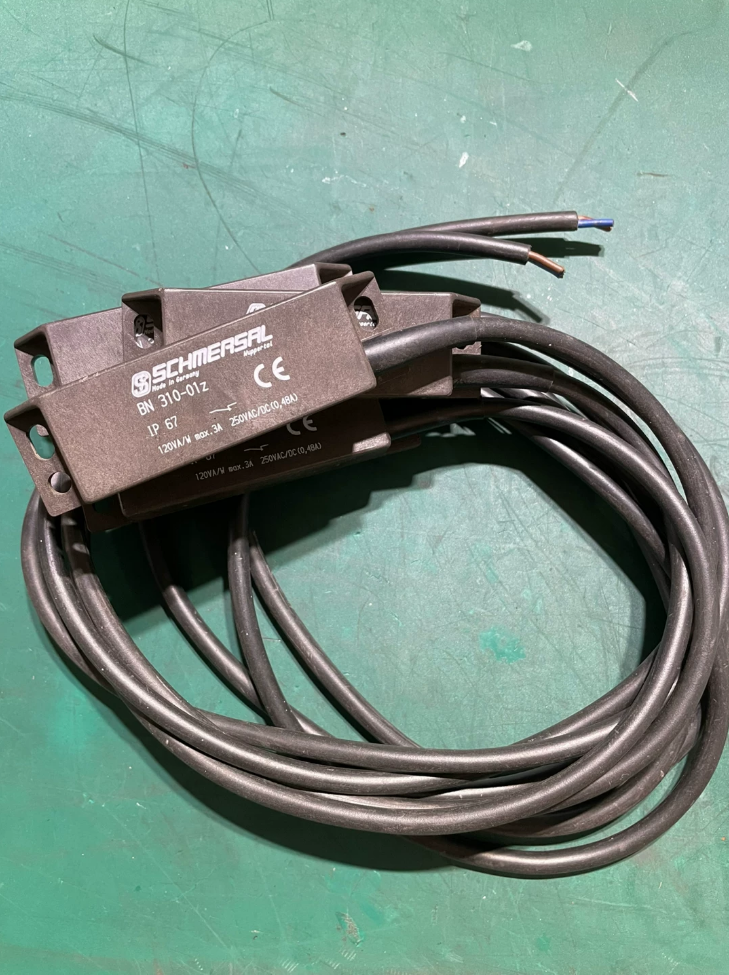

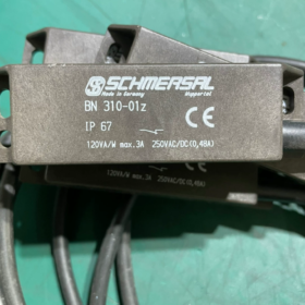
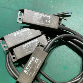
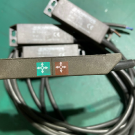
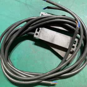

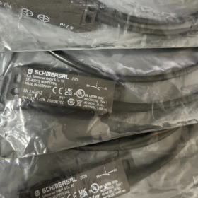
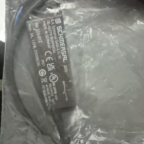
Basic Information
- Brand & Origin: SCHMERSAL, Germany
- Full Model No.: BN 310-01Z
- Factory Order Codes:
1m standard cable version: 101133844
BN310-01Z 3.0m cable version: 101180919
- Product Type: Single Normally Closed (NC) Reed Magnetic Proximity Switch (Safety Door Magnetic Switch)
- Operating Principle: Contact-free magnetic actuation with hermetically sealed reed contacts; used with dedicated magnetic actuators
- Core Electrical & Mechanical Specifications
2.1 Contact Ratings
Contact Configuration: 1 Normally Closed contact (01Z = single NC)
Max Switching Voltage: AC250V / DC250V
Max Switching Current: 3A
Rated Switching Power: 120VA (AC) / 120W (DC)
Operate/Release Delay: 0.3~0.6ms; Max Switching Frequency: 300Hz
Mechanical Service Life: ≥1 billion switching cycles
2.2 Overall Dimensions & Wiring
Housing Dimension: 88mm (L) × 25mm (W) × 13mm (T)
Cable Spec: 2-core PVC cable H03VV-F, cross-section 0.75mm²
Standard Cable Length: 1m; Optional extended lengths: 3m/5m/10m
Housing Material: Glass-fiber reinforced thermoplastic, slim flat design
Net Weight: 75g
2.3 Environmental Protection & Operating Conditions
Protection Class: IP67 (dust-tight, protected against splashing water, suitable for dusty & humid workstations)
Operating Temperature Range: -25℃ ~ +75℃
Vibration Resistance: 10~55Hz, amplitude 1mm; Shock Resistance: 30g/11ms
Actuation Mode: Side magnetic sensing; Effective sensing distance: 3~60mm (depends on matched actuator model)
Repeat Positioning Accuracy: ±0.3mm
2.4 Certifications
CE, cULus; Compliant with EN IEC 60947-5-2; Special certification for elevator industry
- Model Code Explanation
BN310 01 Z
BN310: Slim flat reed switch series
01: 1 contact set
Z: Normally Closed (NC) contact output
Same Series Comparison
BN310-01Z: Single NC (widely used for safety circuits)
BN310-10Z: Single Normally Open (NO)
BN310-RZ: Changeover contact (1NO+1NC)
- Wiring Definition (2-core cable)
S/rd Red Wire: One terminal of reed contact
N/gn Blue Wire: The other terminal of reed contact
Circuit Logic:
Magnet approaches → Contact closes; Magnet moves away → Contact opens (NC safety circuit cuts off, machine stops)
- Typical Application Scenarios
- Position monitoring for safety guard doors & protective covers on machine tools and automated production lines
- Car door / landing door position detection for elevators (compliant with original elevator standards)
- Safety door interlock monitoring for packaging machinery, injection molding machines and conveyors
- Contact-free position signal collection for small equipment cabinet doors and safety shields
Advantages: No mechanical wear, oil & splash water resistant, ultra-long service life, compact mounting footprint
- Matching Accessories & Selection Guidelines
- Only SCHMERSAL original BN-series magnetic actuators (BP10N/BP10S etc.) are allowed; generic magnets cause unstable sensing distance
- IP67 rating tolerates washdown environments, yet permanent submersion is prohibited; install away from strong electromagnetic interference sources
- Safety circuit applications are recommended to be wired in series with safety relays to meet machinery safety standards
- Alternative Models within the Series
Compact short-distance variant: BN20 series
Changeover contact solution: BN310-RZ
Extended cable options: BN310-01Z 3M/5M/10M
SCHMERSAL BN310-01Z Magnetic Safety Switch Installation Manual
Document Information
Model: BN310-01Z (1NC single normally closed reed magnetic switch)
Factory Standards: EN IEC 60947-5-2, EN 1088 safety door standard
Applicable Equipment: Machine tool safety doors, elevator landing/car doors, automated machinery guard interlocks
Target Users: Qualified electrical engineers, equipment installation & maintenance technicians
- Mandatory Pre-Installation Safety Rules
- Electrical Safety
All wiring, disassembly and assembly work must be performed with full power cut off; hot plugging of cables is strictly forbidden. Safety circuits shall be paired with SCHMERSAL SRB/AES series safety relays to fulfill safety monitoring requirements.
- Mandatory Use of Original Accessories
Only SCHMERSAL original BP-series magnetic actuators (BP10/BP15/BP20/BP31/BP34/BP21) are permitted. Generic high-strength magnets lead to false switching, degraded precision and drastically shortened service life.
- Material Restrictions for Mounting Surfaces
Switch and actuators shall not be mounted directly on ferromagnetic steel plates. For steel mounting bases, non-ferromagnetic spacer pads with thickness ≥20mm (plastic/aluminum/copper) must be fitted; otherwise sensing distance will be severely reduced.
- Tamper-Proof Requirements
For safety door applications, anti-torx security screws shall be used to prevent intentional short-circuiting of safety circuits. The switch and actuator shall never serve as mechanical limit stops to avoid housing cracking under compression.
- Environmental Limits
Operating temperature: -25℃ ~ +75℃; IP67 protection withstands splash washing, permanent submersion is prohibited. Keep clear of high EMI sources such as inverters, high-power contactors and electromagnets.
- Product Specifications & Dimensions
2.1 Switch Body Parameters
Profile: Flat housing 88mm (L) × 25mm (W) × 13mm (T)
Mounting Structure: Slotted long holes on top & bottom housing for fine adjustment of sensing distance forward/backward
Cable: 2-core H03VV-F PVC cable, 0.75mm² cross-section; standard 1m, optional 3/5/10m
Cable Color Definition: Red = S, Blue = N (two terminals of NC reed contact)
Contact Capacity: AC250V/3A, 120VA; DC250V/3A, 120W
Repeat Positioning Accuracy: ±0.3mm; Mechanical Life ≥1 billion cycles
2.2 Standard Sensing Distance Sn for Matched Actuators
| Actuator Model | Nominal Sensing Distance | Dual-Actuator Combined Sensing Distance |
| BP10 | 5mm | 17mm |
| BP15 | 6mm | 17mm |
| BP20/BP31 | 20mm | — |
| BP12 | 10~30mm | — |
| BP34 | 5~20mm | — |
| BP21 | 25~50mm | — |
- Step-by-Step Mechanical Installation Procedures
Step 1: Mounting Position Planning
- Fix the switch to stationary machine frames, mount the actuator on movable guard doors/covers. Side-by-side parallel actuation required: the sensing face of the housing must align flat against the actuator surface.
- Maintain minimum spacing ≥50mm between multiple BN310 switches on one cabinet to avoid mutual magnetic interference and false triggering.
- Mounting surfaces must be flat without burrs or protrusions to prevent housing deformation under stress.
Step 2: Fitting Isolation Spacers (Mandatory for Steel Frames)
Steel frame → ≥20mm non-ferromagnetic spacer pad → BN310 switch body; fit identical spacers between steel door panels and actuators. Direct mounting without spacers is allowed for aluminum, stainless steel or plastic frames.
Step 3: Securing the Switch Body
- Thread M3/M4 screws through slotted mounting holes and fasten loosely without full tightening.
- Fully close the guard door, bring the actuator close to the switch sensing face and set the nominal gap per actuator model.
- When the door is fully closed, the actuator must stay within rated sensing range; when fully open, separation distance must exceed maximum release distance to guarantee reliable contact opening.
- Adjust position via slotted holes, test switching logic, then fully tighten screws diagonally with torque 0.8~1.2N·m; over-tightening that crushes the housing is forbidden.
Step 4: Actuator Mounting & Alignment Calibration
- Actuator surface must run perfectly parallel to switch sensing face; tilting over 10° causes complete failure.
- With door closed, actuator center must align with switch sensing zone center, vertical offset ≤3mm.
- Ensure no collision or friction between cables and switch during full door travel; reserve cable slack to avoid tension when the door opens to maximum angle.
Step 5: Cable Routing & Protection
- Route cables inside cable ducts or corrugated tubes to prevent sheath damage from sharp edges.
- Minimum cable bending radius ≥5× outer cable diameter; sharp right-angle folds are prohibited.
- Leave slack at cable entry to avoid tension pulling the switch; fit cable sleeves for workstations with cutting fluid or heavy oil contamination.
- Electrical Wiring Specifications
4.1 Core Wire Definition
BN310-01Z is a passive reed switch with single NC two-wire contacts, no auxiliary power supply required:
Red wire S: First contact terminal
Blue wire N: Second contact terminal
4.2 Circuit Logic
Guard door closed (actuator in position): Contact closed, circuit conductive
Guard door open (actuator separated): Contact open, safety circuit interrupted, machine shuts down
4.3 Three Standard Wiring Schemes
Scheme 1: Safety Relay Safety Circuit (Recommended for Machine Tools & Elevators)
Wire all BN310-01Z switches in series and connect to the input circuit of SRB safety relays:
Power supply AC230V / DC24V → Series-connected red-blue wires of all switches → Safety relay input terminals
Opening any guard door breaks the circuit; safety relay cuts output to main contactors.
Scheme 2: PLC Digital Input (Passive Dry Contact)
For NPN sink-type PLC:
DC24V+ → Switch red wire; Switch blue wire → PLC digital input terminal X; PLC common COM terminal connected to 0V
Door closed: Input channel energized and indicator lit; Door open: Input channel de-energized.
Scheme 3: Auxiliary Control Relay Circuit
AC220V Live Line → Switch red wire; Switch blue wire → Relay coil; Coil opposite terminal connected to Neutral Line
Door closed: Relay coil energized; Door open: Relay coil de-energized.
4.4 Wiring Prohibitions
- Do not exceed rated load AC250V/3A; never drive high-power contactors directly.
- Avoid routing control cables parallel with inverter power cables in the same duct; electromagnetic interference causes intermittent disconnection.
- Strip wire insulation length limited to 3~5mm; prevent stray copper strands from short-circuit; fully tighten terminal lugs to avoid overheating.
- Mandatory Post-Installation Commissioning Tests
- Power-Off Continuity Test
Set multimeter to continuity mode and connect probes to red & blue wires. Continuity alarm sounds when door closed (actuator adjacent); no continuity signal when door fully open — logic confirmed normal.
- Gap Limit Test
With door closed, shift actuator ±2mm within nominal sensing range while maintaining continuity. Gradually pull actuator away beyond rated Sn; contact must open reliably without hysteresis sticking.
- Full Stroke Opening/Closing Cycle Test
Open and close the door repeatedly for 50 cycles; verify no random disconnection or jamming; inspect cables for tension or abrasion.
- Electromagnetic Interference Test
Power on full machine, start/stop inverters and contactors; confirm no unexpected disconnection of the switch. If false triggering occurs, increase separation between control and power cables or install shielded ducts.
- Fault Troubleshooting Matrix
| Fault Phenomenon | Root Causes | Remedial Actions |
| No signal with door closed, circuit permanently open | 1. Mismatched/reversed-polarity actuator | Replace with original actuator; fit ≥20mm non-ferromagnetic spacer; re-calibrate parallel alignment |
| 2. Missing non-ferromagnetic spacer on steel base, insufficient magnetic signal | ||
| 3. Tilted or misaligned actuator | ||
| Contact remains closed with door open, loss of safety function | 1. Excessively small closing gap causing magnetic hysteresis adhesion | Increase door closing gap; maintain ≥50mm spacing between switches; clean metal debris from housing face |
| 2. Magnetic cross-talk between multiple switches | ||
| 3. Ferromagnetic metal shavings adhered to sensing surface | ||
| Random intermittent disconnection during operation | 1. Cable tension / internal wire fracture | Re-route cables with slack reserve; separate control & power wiring; retighten all mounting fasteners |
| 2. EMI from adjacent power cables | ||
| 3. Loose mounting screws due to vibration | ||
| Housing water ingress & failure | IP67 only resists splashing, not continuous submersion; damaged seal at cable entry | Avoid underwater installation; replace damaged cables and seal cable gland with silicone sealant |
- Maintenance & Disassembly Procedures
- Regular Maintenance Cycle
Dusty/oily workstations: Monthly inspection
Clean dry workshops: Quarterly inspection
Inspection items: Screw tightness, cable sheath integrity, metal debris clearance on sensing surface.
- Disassembly Process
Cut full machine power → Disconnect cable terminals inside control cabinet → Loosen mounting screws → Remove switch and actuator; never pull cables orcefully to extract components.
- End-of-Life Disposal
Dispose as electronic & electrical waste per local regulations; discontinue use immediately if internal glass reed tube cracks.
- Strict Installation Forbidden Operations
- Using generic third-party magnets instead of SCHMERSAL original BP-series actuators
- Direct mounting on steel surfaces without non-ferromagnetic isolation spacers
- Mounting actuator tilted at an angle relative to switch sensing face
- Sharp hard bending or permanent tension applied to cables
- Performing wiring/disassembly with power live
- Spacing between multiple switches less than 50mm
- Using switch/actuator as mechanical stop bearing impact loads
- Connecting safety circuits directly to main power circuits without safety relay supervision
- Original Factory Matching Order List
- BN310-01Z switch body (1/3/5/10m cable options; standard 1m order code: 101133844)
- Matching magnetic actuators: BP10 / BP15 / BP20 as required
- Mounting accessories: 20mm plastic isolation spacers, M4 anti-torx security screws, cable corrugated tubes
- Supporting safety relays: SRB300, AES1235





NH42-63-318x560.png "CHINT PC-type automatic transfer switches (ATS)NH42-63/4SZ")



