 Contactor,circuit breaker,solar inverter,electric meter,solar batteries


- Product Overview
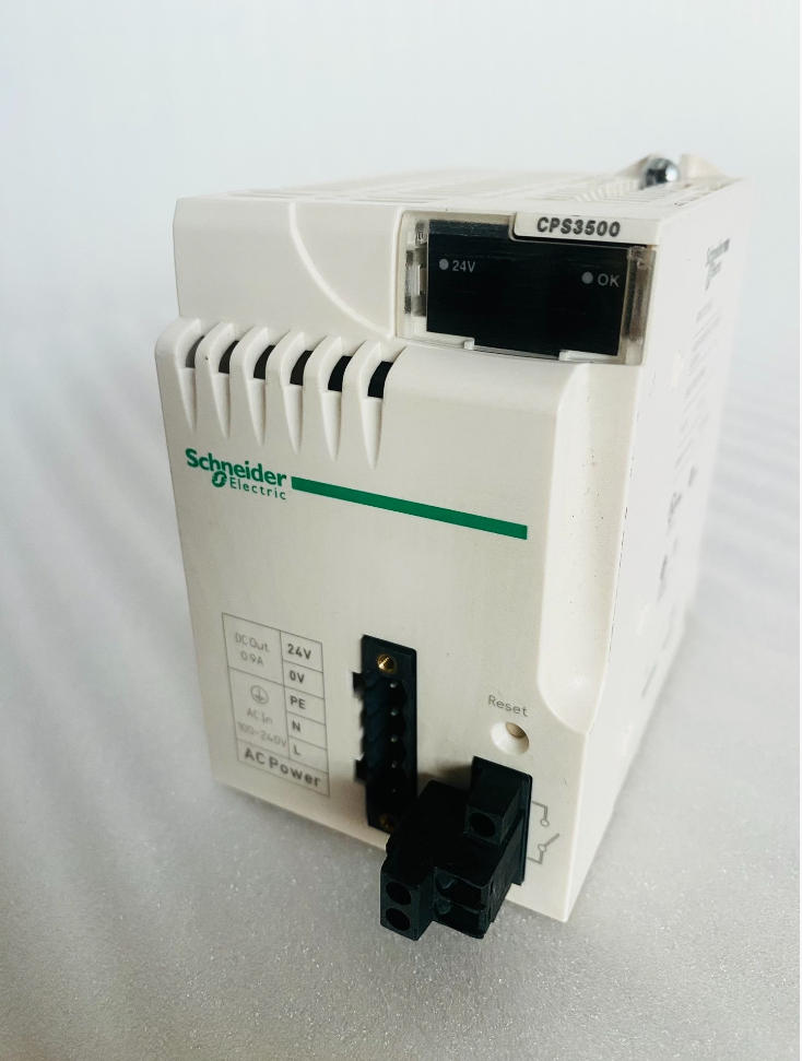
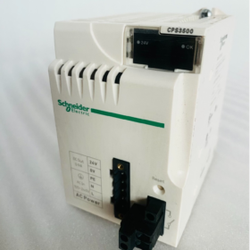
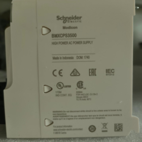
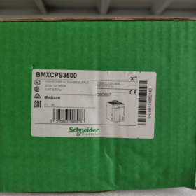
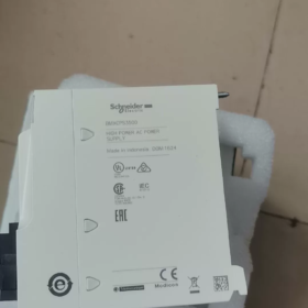
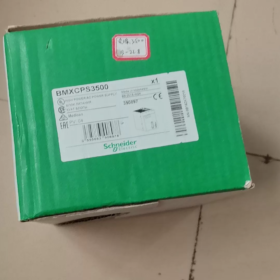
Model: BMXCPS3500
Series: Modicon X80 Rack-mounted Power Supply (Compatible with M340 / M580 PLCs)
Positioning: 36W standard AC input backplane power supply for medium & large X80 racks, with isolated 24V sensor output built-in
Derivative Model: BMXCPS3500H (Wide-temperature version, -25℃ ~ +70℃)
Model Code Breakdown
BMX-CPS-3500
BMX: Modicon X80 platform series
CPS: Control Power Supply rack power module
3500: 36W wide AC voltage high-power variant
- Core Electrical Specifications
2.1 Input Ratings (AC)
Nominal Voltage: 100~240V AC
Full Wide Voltage Range: 85~264V AC (Universal for global power grids)
Frequency: 47~63Hz (50/60Hz compatible)
Input Current: 1.04A @115V / 0.52A @240V
Inrush Current: 30A @120V / 60A @240V (Built-in soft start)
Apparent Power: 120VA
Input Fuse: Non-replaceable internal fuse
2.2 Three Isolated DC Outputs (Total Rated Power: 36W)
| Output Channel | Voltage | Rated Current | Power | Application |
| Logic Power | 3.3V DC | 4.5A | 15W | CPU, backplane bus, I/O logic chips |
| Main Rack 24V | 24V DC | 1.3A | 31.2W | CPU modules, digital/analog I/O, communication modules |
| Isolated Sensor 24V | 24V DC | 0.9A | 21.6W | 4-20mA transmitters, field sensors, valves |
> Key Limitation: All three channels cannot run at full load simultaneously; maximum total output power of the unit is 36W.
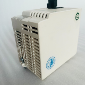
2.3 Mechanical & Environmental Specifications
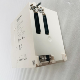
Overall Dimensions: 242.4 × 35 × 110 mm (Single-slot X80 rack module)
Net Weight: 0.36kg
Protection Class: IP20 (For cabinet installation only)
Standard Operating Temperature: 0℃ ~ +60℃
Wide-temperature Model 3500H: -25℃ ~ +70℃ (Automatic power derating at high temperatures)
Storage Temperature: -40℃ ~ +85℃
Humidity: 5%~95% RH, non-condensing
MTBF: 4.3 million hours (Continuous operation at 25℃)
2.4 Safety & EMC Certifications
CE, UL508, CSA, RCM, EAC, ATEX explosion-proof certification
Compliant Standards: EN 61131-2, EN 61000-6-2/6-4, EN 61010-2-201
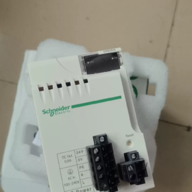
- Front Panel Interfaces & Functions
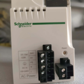
- 5-pin Main Terminal Block
L/N: AC mains input
PE: Protective Earth
24V+/0V: Isolated sensor power output (0.9A)
- 2-pin Alarm Relay Terminal Block
Passive dry contact; contacts open upon power failure; connect to upper-level alarms or audible/visual annunciators
- Dual LED Status Indicators
OK (Green): Main rack power normal; Off = Backplane power fault
24V SENSOR (Green): Sensor 24V output normal; Off = Short circuit / overload on sensor circuit
- RESET Button: Cold restart of the rack, quick reset for CPU and backplane bus
- Built-in Protection Mechanisms
Input Side: Overcurrent fusing, surge suppression
Output Side: Overvoltage (OVP), Overcurrent (OCP), short-circuit latch-off, overtemperature (OTP)
Independent isolated short-circuit protection for sensor circuit, no impact on PLC rack power supply
Fault Latch: After clearing short circuit, power cycle or press RESET to restore operation
- X80 Power Supply Selection Comparison within the Same Series
| Model | Input Type | Total Power | Sensor 24V Current | Applicable Rack Scale |
| BMXCPS2000 | 85~264V AC | 20W | 0.45A | Small racks ≤12 slots |
| BMXCPS3500 | 85~264V AC | 36W | 0.9A | Medium & large multi-rack systems |
| BMXCPS3500H | 85~264V AC | 36W | 0.9A | Severe high/low temperature sites |
| BMXCPS4002 | 24V DC | 40W | 1.6A | DC-powered control cabinets, on-board equipment |
Selection Conclusion for Replacement
- Downward Replacement: BMXCPS2000 can be used if total load <20W, but sensor power capacity is halved; not directly interchangeable for high-load systems.
- Upward Replacement: No higher-power AC-input X80 power supply available. Multiple BMXCPS3500 units shall be configured for separate racks in multi-rack systems.
- Low-temperature Applications: BMXCPS3500H is mandatory for field temperatures below 0℃; standard 3500 will derate or trigger faults at low temperatures.
- Typical Application Scenarios
- Medium & large Modicon M340/M580 PLC control systems
- Main control cabinets for water treatment, metallurgy, chemical, packaging machinery and building automation
- Projects requiring independent isolated 24V power for transmitters, flow meters and pressure sensors
- Centralized power supply for multi-expansion racks (BMXXBP series backplanes)
- Troubleshooting Matrix
| Fault Phenomenon | Root Cause | Handling Procedures |
| Both LEDs fully off | No AC input, loose wiring, blown internal fuse | 1. Measure L/N voltage; 2. Tighten terminals; 3. Replace module if fuse blown |
| OK LED off, Sensor LED on | Total rack load exceeds 36W, backplane short circuit | 1. Calculate total power consumption of all modules; 2. Remove redundant I/O modules; 3. Inspect backplane for short circuit |
| Only 24V Sensor LED off | Short circuit / overload on sensor circuit | 1. Disconnect external sensor cables; 2. Locate short circuit in field wiring; 3. Restart power supply after recovery |
| Indicators flicker after running for a period | Ambient temperature over 60℃, poor heat dissipation | Install cabinet cooling fan, replace with 3500H wide-temperature model, reduce rack load |
| Alarm relay remains open | Protection triggered on any output channel | Power off for 5 minutes to cool down, inspect short circuit and overloaded loads |
- Installation & Wiring Prohibitions (Hard Rules)
- Do not share the same circuit with high-power inverters and contactors; separate isolated power supply is required.
- Sensor 24V cables shall not be routed in the same trunking as power cables to avoid interference.
- The module must be reliably connected to PE protective earth; otherwise EMC interference may cause false alarms.
- Total load of a single 3500 unit is strictly limited to 36W max; separate power supplies must be used for multiple racks.
- Do not plug/unplug the module during operation (no hot-swap design); replace only after power cut-off.
- Compatible Backplanes
Fully compatible with all BMXXBP X80 backplanes: BMXXBP0400 / 0600 / 0800 / 1200, etc.
Incompatible: Old-generation Quantum BMEXBP series backplanes; mixed use is forbidden.
Complete Installation Specification for Schneider BMXCPS3500
- Core Installation Structure (Two Layers)
1.1 Base Layer: 35mm Standard DIN Rail Mounting (Cabinet Rear Panel)
The unit is equipped with a built-in DIN35 standard snap-on base, compatible with national standard 35mm electrical mounting rails (AM1 ED rail).
Module width: 35mm, single-slot occupation; dimensions: 242.4 (H) × 35 (W) × 110 (D) mm
Snap structure: Dual upper & lower elastic snaps for rail fastening without screws; top/bottom latches prevent detachment
Rail mounting steps:
- Secure 35mm DIN rail to cabinet rear panel, ensure rail is level and undeformed
- Hook the module’s bottom snap onto the lower edge of the rail first, then push the upper part of the module upward until a “click” sound confirms full engagement
- Fully lock both upper and lower snaps; no vertical looseness under pulling force. To remove, pry open upper/lower snaps with a flat screwdriver.
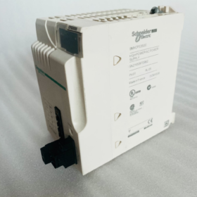
1.2 Upper Layer: X80 Dedicated Backplane Slot Installation (Core Rack Power Connection)
BMXCPS3500 must be inserted into BMXXBP series X80 rack backplanes to supply power to CPU and I/O backplanes; standalone operation without backplane is not allowed.
Compatible Backplane Models
Only compatible: BMXXBP0400 / 0600 / 0800 / 1200 (including H wide-temperature variants)
Mixed Use Forbidden: Old BMEXBP…02 Quantum backplanes with mismatched physical connectors.
Standard Backplane Mounting Procedure (Power Off Mandatory, Hot Swap Prohibited)
- Cut off power to the whole unit and disconnect AC input
- Align the metal guide slots on the rear of the power module with upper/lower rails of the rack backplane, slide horizontally smoothly to the bottom of the slot
- After full insertion, backplane bus gold fingers are fully mated; front face of the module aligns flush with other I/O modules
- Built-in left & right locking latches on the module, snap inward to lock onto the rack and prevent loosening under vibration
- Power supply shall be installed in the 1st leftmost slot of the rack as priority (Official recommended layout); one CPS3500 for each independent backplane in multi-rack systems.
- Mounting Attitude & Tilt Restrictions
- Standard Attitude: Vertical upright installation (cabinet rear panel vertical, module vertical top-to-bottom) for vertical convection cooling airflow, optimal heat dissipation
- Allowable Tilt: Full-load operation permitted within ±30° panel tilt; derating required if tilt exceeds 30°, cabinet internal temperature ≤40℃
- Strictly Forbidden: Horizontal flat or upside-down mounting – airflow blocked, frequent overtemperature tripping, drastically shortened service life.
- Mandatory Heat Dissipation Clearance Requirements (Hard Installation Gaps)
The module relies on natural air cooling via top & bottom ventilation holes; clearances must be reserved:
Above & below the module: ≥20mm free space, unobstructed by cable ducts or other components
Left & right sides of the module: ≥10mm, no tight contact with adjacent modules
Horizontal distance between heat-generating components (inverters, contactors) and power supply inside cabinet ≥50mm
Cooling fan recommended for sealed small cabinets; replace with BMXCPS3500H wide-temperature model if ambient temperature >55℃.
- Terminal Accessory Installation (Wiring Matching Parts)
Standard factory supply: Screw-type terminal block BMXXTSCPS10; Spring push-in terminal block BMXXTSCPS20 available as separate order.
- 5-pin main power terminal (L/N/PE/24V circuit/Sensor 24V): Insert horizontally into lower front interface of module, lock via built-in snap
- 2-pin alarm dry contact terminal: Adjacent to the right of 5-pin terminal, used for fault alarm output
- Terminal Removal: Pinch both side snaps of terminal and pull straight outward; diagonal pulling is prohibited to avoid broken pins.
- Installation Environment & Protection Specifications
- Protection Class IP20, cabinet installation only; no direct exposure to outdoor environment, dust or moisture.
- Flat, burr-free mounting surface; firmly fixed DIN rail; rail end stops required for high-vibration operating conditions.
- PE protective earth wire must be reliably connected to cabinet earth bar to reduce EMC interference.
- No power derating required for altitude ≤2000m; 10% load derating mandatory above 2000m.
- Installation Prohibitions (Absolute Forbidden Operations)
- Plug/unplug module or wiring terminals while powered – risk of burning backplane bus and power supply.
- Unlocked fixing latches cause poor backplane contact and system shutdown under long-term vibration.
- Insufficient top/bottom heat dissipation space or close contact with cable ducts triggers overtemperature protection under high temperature.
- Upside-down / flat mounting blocks cooling airflow.
- Mixed use of old BMEXBP backplanes with mismatched physical connectors; forced insertion damages gold fingers.
- Single power supply driving multiple independent backplanes leads to overload protection triggered when total power exceeds 36W.
- Supplementary Redundant Power Supply Installation (Multi-Power Scenarios)
For redundant power supply, install one BMXCPS3500 in two separate slots of the same rack, each fed by an independent AC circuit. The backplane performs automatic redundant switching. Reserve ≥15mm heat dissipation gap between the two power supplies.

 Inductive Proximity Sensor")
")


")
NH42-63-318x560.png "CHINT PC-type automatic transfer switches (ATS)NH42-63/4SZ")


