 Contactor,circuit breaker,sensor,Encoder,PLC,Converter

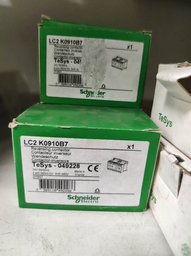

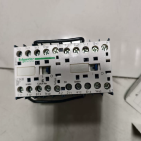
Product: TeSys-K 3-pole reversing contactor, manufactured in France, equipped with built-in mechanical interlock and pre-assembled reversing power busbar
Model Decoding
LC2K: Reversing contactor series (LC1K stands for single contactor; LC2K = pre-assembled reversing assembly of two contactors)
09: AC-3 rated operational current 9A
01: Auxiliary contact configuration 1 Normally-Closed (1NC)
B7: Coil voltage AC24V, 50/60Hz
Core Electrical Specifications
| Item | Parameter |
| Main circuit poles | 3P‑3NO |
| AC‑3 operational current | 9A |
| Rated motor power | 2.2kW(230V) / 4kW(380‑415V) |
| Max main circuit voltage | 690V AC |
| Coil | AC24V 50/60Hz; Inrush 30VA, Hold‑in 4.5VA |
| Auxiliary contact | 1NC instantaneous |
| Conventional thermal current Ith | 20A |
| Utilization category | AC‑3, AC‑3e, AC‑4, AC‑1 |
| Interlock | Built‑in mechanical interlock |
| Terminal connection | Screw terminals, 0.75‑4mm² conductor; Torque 0.8‑1.3N·m |
| Mounting | DIN35 rail / Plate mounting with screws |
| Overall dimension | W90 × H58 × D57mm, Weight 0.39kg |
| Mechanical endurance | 5 million cycles; Electrical endurance 1.3 million cycles (AC‑3) |
| Operating ambient temperature | -25~+50℃ |
| Certifications | CCC, UL, CE, EAC |
Application Scenarios
Three-phase motor forward/reverse control (conveyors, winches, rollers, valve actuators). The phase-reversing busbar is factory pre-fitted, no manual phase swap required for main circuit wiring. Electrical interlock shall be implemented as secondary protection.
Similar Reference Models
LC2K0910B7: Coil AC24V, auxiliary 1NO (Normally-Open)
LC2K0901M7: 1NC auxiliary contact, coil AC220V
LC2K0901F7: 1NC auxiliary contact, coil AC110V
Selection & Substitution Notes
- LC2K is a complete reversing unit. Do not assemble two separate LC1K contactors manually, as factory-fitted reversing busbar and matched mechanical interlock will be missing.
- For domestic alternative: verify parameters: 9A, AC24V coil, 1NC auxiliary contact, integrated mechanical interlock for reversing operation.
- Spare-part inspection points: Measure resistance of both coils; check mechanical interlock for jamming; inspect main contacts for ablation; verify terminal tightening torque.
Note: LC2K0901B7 is an imported model. Local stock is often limited with long lead-time.
Schneider LC2K0901B7 (TeSys-K Reversing Contactor) Installation Manual
This manual is compiled in accordance with Schneider original Instruction Sheet, for model LC2K0901B7, 3P, 9A AC-3, 1NC auxiliary contact, AC24V 50-60Hz coil, built-in mechanical interlock and pre-assembled reversing power busbar.
⚠️Safety prerequisite: Installation and wiring shall only be performed by qualified electricians. Completely disconnect upstream power supply before any work. IP20 degree of protection. Device must be installed inside closed electrical cabinet, open-air operation is forbidden.
Table of Contents
- Product Overview
- Summary of Technical Specifications
- Ambient Conditions & Mechanical Mounting
- Electrical Wiring Instructions
- Terminal Torque & Cable Specifications
- Control Circuit & Mandatory Interlock Requirements
- Pre-power-on Check List
- Commissioning Procedure
- Maintenance & Troubleshooting
- Ways to Obtain Original PDF Manual
- Product Overview
LC2K0901B7 is factory pre-assembled motor forward-reverse reversing contactor, assembled from two LC1K contactors plus integrated mechanical interlock and pre-fitted reversing power busbar. Two-phase swap is completed inside factory busbar; manual phase swapping on main circuit is NOT required.
Main contacts: 3 Normally-Open; Auxiliary contact: 1 Normally-Closed (1NC) instantaneous contact
Coil: AC24V 50/60Hz; Inrush 30VA, Hold-in 4.5VA
AC-3 9A; Rated motor power 4kW@400V; 2.2kW@230V
Mounting: DIN35 rail mounting / Plate mounting with screws
Dimension: W90mm × H58mm × D57mm, Weight 0.39kg
- Installation Ambient Conditions
- Operating ambient temperature: -25℃ ~ +50℃; Storage temperature -50~+80℃
- Altitude: No derating ≤2000 m; derating is required above 2000 m
- Environment: Free of explosive dust and corrosive gas, well-ventilated; avoid direct sunlight.
- Cabinet installation: Maintain ≥10 mm clearance top and bottom for heat dissipation. Side-by-side compact mounting is permitted; extra clearance is required for high-temperature environment.
- Vibration & shock: Complies with IEC60068-2-6. Keep away from heavy-vibration equipment inside cabinet.
- Mechanical Mounting
3.1 DIN-rail mounting (preferred)
- Hook bottom latches of contactor onto DIN35 rail.
- Press down contactor body until latches click and lock firmly.
- Removal: Pry down bottom latch with flat-blade screwdriver, lift contactor upwards.
3.2 Plate mounting with screws
Use M3/M4 screws through mounting holes on housing. Do not over-tighten to prevent cracking plastic housing. Mounting base must be flat and distortion-free.
Mounting orientation: Vertical installation with terminals facing upward. Horizontal or upside-down mounting is prohibited, which will shorten mechanical service life.
- Electrical Wiring Instructions
For LC2K integrated reversing contactor: Reversing power busbar is factory fitted. Do NOT disassemble it. Disassembly may cause short-circuit risk during forward/reverse switching.
Main-circuit terminals
L1, L2, L3: Three-phase power supply input
T1, T2, T3: Connect to three-phase motor U, V, W
Important: Do NOT swap phases on T side. Phase reversal is realized by internal pre-assembled busbar. Re-swapping phases on output side will result in identical rotation direction for both forward and reverse commands.
Coil terminals
A1, A2: Coil of forward contactor (AC24V)
A1, A2: Coil of reverse contactor (AC24V)
Strictly apply AC24V coil voltage. Applying 220V will burn coil instantly. Allowable coil operating voltage range: 0.8~1.15×Uc, i.e. 19.2V-27.6VAC.
Auxiliary contact terminals
13-14: 1NC normally-closed auxiliary contact, used for control-circuit interlock and status feedback.
- Terminal Torque & Cable Specifications
Screw-clamp terminals, Phillips No.2 / 6 mm flat-blade screwdriver
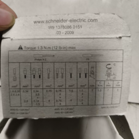
Tightening torque: 0.8-1.3 N·m. Over-tightening cracks plastic terminal base; insufficient torque causes overheating.
Compatible conductors:
Solid single-core: 1.5-4 mm²
Flexible without ferrule: 0.75-4 mm²
Flexible with cable ferrule: 0.34-2.5 mm²
-Stripping length: 5-6 mm. Exposed bare copper must not touch adjacent terminals to prevent phase-to-phase short-circuit.
- Control-circuit & Mandatory Interlock Requirements
⚠️This unit is equipped with mechanical interlock only. Mechanical interlock cannot completely eliminate risk of simultaneous closure of both contactors. Electrical interlock via auxiliary contacts in secondary control circuit is MANDATORY, otherwise catastrophic three-phase short-circuit may occur.
- Mechanical interlock: Internal mechanical mechanism physically permits only one contactor to close at one time. Risk of jamming-caused failure still exists.
- Electrical interlock wiring: Series NC auxiliary contact of forward contactor into reverse coil circuit; series NC auxiliary contact of reverse contactor into forward coil circuit.
- Control supply: AC24V. Coil circuits A1/A2 and A1’/A2′ are isolated; avoid wrong common connection.
- Recommended configuration: Fit thermal overload relay for motor overload protection; upstream short-circuit protection by 25A gG fuse.
- Complete Pre-power-on Check-List
- Mechanical check: Manually actuate contactor operating mechanism. Mechanical interlock shall work properly; simultaneous manual closing of both contactors must not be possible; operation shall be smooth without jamming.
- Wiring inspection: All terminals tightened to 0.8-1.3 N·m; no loose wire strands or exposed bare copper; pre-assembled reversing busbar intact and undamaged.
- Coil verification: Confirm control voltage is AC24V to avoid over-voltage damage.
- Circuit test: Multimeter verification for correct electrical interlock wiring; no short-circuit between L1-L2-L3 on main circuit.
- Motor side: Motor insulation resistance normal, motor wiring correct.
- Commissioning
- Disconnect motor load; energize only AC24V control circuit.
- Trigger forward and reverse commands separately: Only one contactor shall pull-in at any time; interlock function valid. Simultaneous pull-in must not occur.
- De-energize, reconnect motor. Re-energize and test forward / reverse rotation direction.
- Observe running status: No abnormal noise or overheating at terminals.
Max operating frequency: 3600 operations per hour. Derate for frequent forward-reverse cycling.
- Maintenance & Troubleshooting
| Fault Phenomenon | Troubleshooting Points |
| Coil energized, contactor refuses to pull‑in | Measure AC24V coil voltage; inspect A1/A2 wiring; check mechanical jamming; measure coil resistance |
| Contactor pulls‑in but motor does not run | Check loose or ablated main‑circuit input/output terminals; inspect contact ablation |
| Instant tripping upon start‑up | Confirm reversing busbar is intact; verify electrical interlock exists; check risk of simultaneous phase‑to‑phase conduction |
| Loud operating noise | Check coil voltage deviation; cabinet resonance; dirt on armature core face |
Service life reference: Mechanical endurance 5 million cycles; Electrical endurance 1.3 million cycles under AC-3 condition.
Periodic maintenance: Retighten terminal torque; inspect contact ablation; remove dust accumulation.
- Access to Original PDF Manual
- Visit Schneider official website and search for LC2K0901B7. Download LC2-K contactor-Instruction Sheet under product documentation section.
- Search for TeSys-K reversing contactor in Schneider China download center.
Note: LC2K0901B7 is imported. Hard-copy printed manual is mostly English-only without full Chinese version. This compiled manual strictly follows original Schneider specifications.
Common Faults of Schneider Contactors (Applicable to TeSys-K LC2K series, also for LC1D, LC1N etc.)
Fault categories: Failure to pull-in; instant drop-out after pull-in; pulled-in but no main-circuit output; humming noise; contact ablation; coil burnout; reversing-contactor unique faults, with troubleshooting guidance.
- Coil energized, contactor fails to pull-in completely
- No voltage or insufficient voltage on control circuit
Phenomenon: Rated coil voltage not measured across A1-A2; operating voltage below 80% of nominal coil voltage.
Root cause: Faulty control supply, broken push-button/interlock contact, loose wiring.
For LC2K reversing unit: Distinguish forward coil A1/A2 and reverse coil A1’/A2’; avoid measuring wrong terminals.
- Open-circuit burnt coil
Measured coil resistance infinite; coil visibly burnt black.
Triggers: Wrong high-voltage supply (e.g. feeding 220V onto 24V coil), sustained over-voltage, high-temperature ageing.
- Mechanical jamming
Foreign debris or plastic fragments inside mechanism; skewed DIN-rail mounting; jammed mechanical interlock of reversing contactor.
Manual actuation of mechanism feels heavy and cannot reach closed position.
- Poor contact of NC auxiliary interlock contact (high-frequency failure on LC2K reversing units)
Oxidized interlock auxiliary contact breaks coil power supply path.
- Coil energized, instant drop-out / chattering after pull-in
- Insufficient coil voltage: Large voltage drop caused by long control cables; voltage below 85% Ue results in insufficient armature holding force.
- Dirt, rust or oil contamination on armature core mating surfaces: Magnetic-circuit gap increases, insufficient holding force, repeated chattering.
- Loose control-circuit connections, intermittent voltage.
- LC2K specific: Half-jammed mechanical interlock, incomplete mechanism travel causes drop-out.
- Contactor pulls-in normally, but motor does not operate (no output on main circuit)
- Loose and over-heated main-circuit terminals: Insufficient screw torque causes thermal oxidation; no load voltage may read normal, voltage collapses under load.
- Ablated / disconnected main contacts: Heavy inrush current, frequent cycling creates pitted carbonized contacts with high contact resistance.
- Open-phase on upstream supply: Blown fuse or damaged upstream circuit-breaker pole.
LC2K reminder: Loosened or detached pre-assembled reversing busbar leads to open-phase. Never remove factory-fitted busbar.
- Loud buzzing / humming noise during operation
- Dust and grease contamination on core mating surfaces, incomplete magnetic closure, typical AC-contactor hum.
- Coil voltage too high or too low.
- Broken short-circuit ring on armature core: Severe noise, contactor replacement is mandatory.
- Cabinet resonance or loose DIN-rail mounting.
- Contact welding (hazardous condition)
After power-off, main contacts remain conducting, motor cannot stop; for reversing contactors this leads directly to phase-to-phase short-circuit.
Root causes:
- Overload, short-circuit surge current; frequent jogging / frequent reversing exceeding operating frequency limit (AC-4 duty).
- Insufficient coil voltage causes contact bounce and arc welding.
- Under-sized contactor rating.
Critical risk for LC2K: Relying solely on mechanical interlock without electrical interlock, simultaneous closure of both contactors creates short-circuit and contact welding.
- Burnt coil
- Wrong applied voltage: Feeding AC220V onto B7 24VAC coil burns coil instantly.
- Sustained over-voltage above 115% nominal coil voltage.
- Mechanism jamming, armature cannot close; coil remains at high inrush current and burns out quickly.
- Excessive cabinet ambient temperature and poor heat dissipation.
- Unique faults for LC2K reversing contactor (forward-reverse)
- Fail to switch rotation direction: Jammed mechanical interlock blocks operation of one contactor.
- Forward works, reverse no output (or vice versa): Loosened / detached pre-assembled reversing busbar, or ablation of main contacts on one unit.
- Tripping immediately upon direction change: ① Factory reversing busbar removed; ② Missing electrical interlock leading to simultaneous pull-in of both contactors.
- Damaged auxiliary contacts: Feedback signal failure and loss of electrical interlock function.
- Over-heating
- Improper terminal torque: Under-torque causes loose overheating; over-torque cracks plastic terminal base.
- Under-sized cable cross-section.
- Ageing contacts with high contact resistance.
- High cabinet temperature, poor heat dissipation with densely-packed adjacent devices.
Quick Field Troubleshooting Workflow
- Power off, manually actuate contactor mechanism to check for mechanical jamming.
- Power-on measurement of actual coil operating voltage.
- Power-off coil-resistance measurement to judge coil integrity.
- With contactor pulled-in, measure input-to-output three-phase voltage on main circuit to locate terminal / contact defects.
- For reversing units: Inspect mechanical interlock, electrical interlock wiring and physical integrity of pre-assembled reversing busbar.
Preventive Recommendations
- For LC2K reversing contactor: Mechanical interlock is not sufficient safety protection; electrical interlock must be implemented.
- Strictly follow specified torque for terminal tightening.
- Derate contactor rating for heavy-duty AC-4 frequent reversing applications.
- Maintain cabinet ventilation; perform periodic dust removal.
Contactor Pull-in Normal, But No Main-circuit Output (Power present yet no load voltage)
Phenomenon: Coil energized, audible pull-in action, status indicator shows closed state; however no voltage appears on load side and motor cannot run. Description applies to LC2K0901B7 reversing contactor and general-purpose AC contactors.
- Terminal & Wiring Failures (Most frequent on-site cause)
- Under-torqued main-circuit screws resulting in loose cable connection
Screws appear tightened yet conductors are not securely clamped. High contact resistance leads to voltage collapse under load.
Specified torque for LC2K terminals: 0.8-1.3 N·m. Too low → loose overheating; too high → cracked plastic housing.
Symptom: Voltage may read normal under no-load condition, but vanishes as soon as load is applied; terminals show discoloration due to heat.
- Insufficient cable stripping length, loose wire strands not fully clamped inside terminal; flexible conductors without cable ferrules.
- LC2K-specific fault: Loosened, detached or fractured pre-assembled reversing busbar. Damage occurs if busbar is disassembled, resulting in open-phase. ⚠️ Do not remove factory-fitted reversing busbar.
- Main-contact internal failure
- Ablated, worn or oxidized main contacts with loss of conduction
Mechanism completes full mechanical travel, yet pitted and carbon-covered main contacts cannot establish electrical conduction.
Measurement method: Under power-off condition, manually hold contactor in closed position; measure resistance L-T for each pole with multimeter. Normal reading is near 0 Ω; hundreds of ohms or infinite resistance indicates damaged contacts.
Triggers: Frequent start-stop, AC-4 jogging, short-circuit surges, end-of-electrical-life condition.
Visual inspection may show no obvious damage while internal contact surfaces are burnt.
- Mechanical offset of contact assembly: Armature reaches closed position, but main contacts are not fully compressed.
- Upstream supply faults (Easily mis-diagnosed as contactor failure)
- One-phase fuse blown or one pole defective on upstream circuit-breaker. Input phase is missing before reaching contactor.
-Troubleshooting priority: First measure three-phase voltage at contactor input terminals L1/L2/L3 to confirm supply integrity.
- Tripped upstream thermal overload relay breaking main power path.
- LC2K Reversing-contactor specific conditions
- Only one rotation direction dead (forward OK / reverse no output, or opposite): Inspect reversing busbar and main contacts of corresponding contactor unit.
- Partially jammed mechanical interlock: Armature appears closed, yet main contacts are not fully pressed internally.
On-site Troubleshooting Sequence
- Step 1: Measure three-phase input voltage L1, L2, L3 at contactor input terminals
Confirm complete three-phase supply, eliminate upstream open-phase.
- Step 2: With contactor kept pulled-in, measure output-side voltage T1, T2, T3
If input voltage is normal while certain output phase reads zero → fault lies within contactor (terminals / contacts / reversing busbar).
- Power-off safe operation: Manually hold contactor closed; measure resistance L1-T1, L2-T2, L3-T3 with ohmmeter
Normal: Near-zero conduction;
Infinite resistance: Contacts not conducting;
High resistance: Ablated contacts or loose terminals.
- Check terminal tightening; inspect physical integrity of pre-assembled reversing busbar (LC2K).
Distinguish Two Similar Phenomena
- ✅ Contactor pulls-in, no main-circuit output: Fault covered above.
- ❌ Contactor repeatedly chatters and cannot stay closed: Caused by insufficient coil voltage or contaminated core faces, different failure mode.
Remedial Actions
Loose terminals: Retighten to specified torque; fit cable ferrules for flexible conductors.
Ablated contacts or damaged reversing busbar: Do NOT file or polish contacts; replace contactor assembly directly. Polishing accelerates contact degradation.
For LC2K reversing unit: Do not dismantle factory-supplied reversing power busbar.










NH42-63-318x560.png "CHINT PC-type automatic transfer switches (ATS)NH42-63/4SZ")



