Contactor,circuit breaker,sensor,Encoder,PLC,Converter





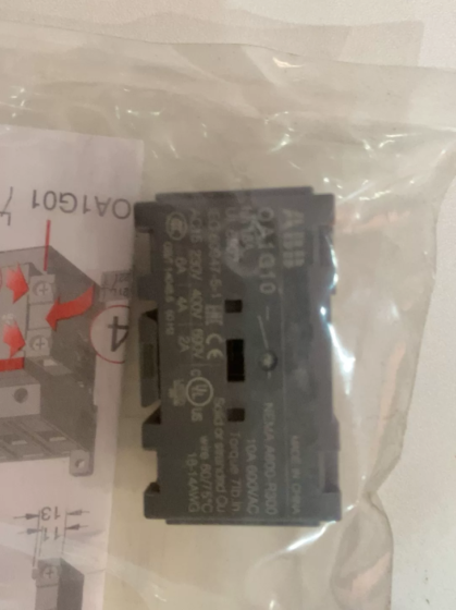
Full Product Name: SIRIUS Classic side-mounted auxiliary contact (lateral auxiliary switch)
Suitable for legacy 3RV1 motor protection circuit breakers, frame sizes S00 / S0 / S2 / S3; screw terminal, 1NO+1NC (1 normally open + 1 normally closed)
Lifecycle: Obsolete (Phase-out). It is an accessory for the older 3RV1 platform; the manufacturer promotes the upgraded 3RV2 platform.
Key Specifications
Contact configuration: 1NO + 1NC
Mounting: Lateral side mounting (distinguished from front-mounted 3RV1901-1E)
Wiring: Screw-clamp terminals
Contact rating: AC-12, max. 6A / 240V AC; commonly used for 24VAC/DC, 220VAC signal feedback in control circuits
Protection: IP20
Application: Passive feedback of circuit breaker ON/OFF status for PLC, indicator lamps and circuit interlocks
Compatible breaker bodies: 3RV10, 3RV11, 3RV13, 3RV14, 3RV16 and other legacy 3RV1 motor protectors; not directly compatible with the new 3RV2 series
Model Code Explanation
3RV1: Legacy SIRIUS motor protection circuit breaker series
3RV19: Accessory group for the 3RV1 series
01: Auxiliary switch
1A: Lateral mounting, 1NO+1NC, screw terminals
Replacement Options (Important)
- If migrating to 3RV2 circuit breakers: Front auxiliary contact 3RV2901-1E (1NO+1NC, screw); lateral type 3RV2901-2E (2NO+2NC)
- If keeping the existing 3RV1 breaker body: Only stock / second-hand 3RV1901-1A is available; 3RV29xx accessories cannot be fitted onto legacy 3RV1 breakers
- Other accessories of the same series for reference:
3RV1901-1E: Front-mounted auxiliary contact, 1NO+1NC
3RV1901-1J: Lateral, 2NO
3RV1901-1C: Lateral, 2NC
Full Accessory List for Siemens 3RV1 (Legacy SIRIUS Motor Protection CB)
Compatible bodies: 3RV10 / 3RV11 / 3RV13 / 3RV14 / 3RV16; frame S00, S0, S2, S3; entire series obsolete. Accessories fit only 3RV1 bodies and cannot be installed on 3RV2
Terminal distinction: -1xxx = screw terminals; -2xxx = spring-cage terminals
- Auxiliary Contacts (Status feedback, reflects CB ON/OFF position)
| Order No. | Mounting Position | Contact Configuration | Remarks |
| 3RV1901-1A | Lateral | 1NO+1NC | Model inquired, screw terminal |
| 3RV1901-1B | Lateral | 2NO+2NC | Screw |
| 3RV1901-1C | Lateral | 2NC | Screw |
| 3RV1901-1J | Lateral | 2NO | Screw |
| 3RV1901-2A | Lateral | 1NO+1NC | Spring-cage |
| 3RV1901-2B | Lateral | 2NO+2NC | Spring-cage |
| 3RV1901-2C | Lateral | 2NC | Spring-cage |
| 3RV1901-1E | Front (transverse) | 1NO+1NC | Screw, most common front type |
| 3RV1901-1F | Front | 2NO | Screw |
| 3RV1901-1D | Front | 2NC | Screw |
| 3RV1901-1G | Front | 1NO+1NC | For low-current / electronic circuits, dust-resistant |
| 3RV1901-0H | Dust cover for front auxiliary contact | — | Protective cap, pack of 10 |
Limitation: Maximum one lateral auxiliary contact per 3RV1 breaker; front-mounted + lateral can be used together.
- Fault Signal Switch (Trip signal, distinguishes overload / short-circuit, not equal to standard auxiliary contact)
| Order No. | Contact Configuration | Remarks |
| 3RV1921-1M | 1NO+1NC | Fault contact, actuates only on overload or short-circuit trip; no action during manual ON/OFF. For PLC fault alarm. |
- Undervoltage Release (UVT, trip on loss of supply)
| Order No. | Coil Voltage |
| 3RV1902-1AB0 | AC24V 50Hz |
| 3RV1902-1AF0 | AC110V 50Hz |
| 3RV1902-1AP0 | AC230V 50Hz |
| 3RV1902-1DC0 | DC24V |
- Shunt Release (SHT, remote tripping)
| Order No. | Coil Voltage |
| 3RV1903-1AB0 | AC24V |
| 3RV1903-1AF0 | AC110V |
| 3RV1903-1AP0 | AC230V |
| 3RV1903-1DC0 | DC24V |
Release rule: Undervoltage release and shunt release are mutually exclusive, cannot be fitted on the same breaker.
- Door-coupled Rotary Operating Mechanism (External cabinet operation, IP65, padlockable)
| Order No. | Shaft Length | Compatible Frame |
| 3RV1926-0B | 130mm | S0 / S2 / S3 |
| 3RV1926-0K | 330mm | S0 / S2 / S3 |
Function: Cabinet door cannot be opened when CB is closed; lockable in OFF position to prevent accidental closing.
- Busbar Modules (Main circuit interconnection for side-by-side mounting)
S00 / S0 Frame
| Order No. | Purpose |
| 3RV1915-1AB | Busbar for 2 breakers |
| 3RV1915-1BB | Busbar for 3 breakers |
| 3RV1915-1CB | Busbar for 4 breakers |
| 3RV1915-1DB | Busbar for 5 breakers |
| 3RV1915-3AB | 2 breakers (with space for accessories) |
| 3RV1915-3BB | 3 breakers (with space for accessories) |
| 3RV1915-3CB | 4 breakers (with space for accessories) |
S2 Frame
| Order No. | Purpose |
| 3RV1935-1A | 2 breakers |
| 3RV1935-1B | 3 breakers |
| 3RV1935-1C | 4 breakers |
| 3RV1935-3A | 2 breakers (with space for accessories) |
- Contactor Link Module (Direct assembly for 3RV1+3RT1 starter group, no extra busbar)
| Order No. | Compatible Assembly |
| 3RA1941-1B | Mechanical & electrical link for 3RV1.41 + 3RT1.4 starter combination |
- Seals, Covers & Other Mechanical Accessories
| Order No. | Description |
| 3RV1920-1A | Seal kit, prevents unauthorised adjustment of current setting dial |
| 3RV1910-1A | Extended terminal cover |
Cross Reference for Migration to 3RV2 Platform
| Legacy 3RV1 Part No. | 3RV2 Replacement |
| 3RV1901-1A (Lateral 1NO+1NC, screw) | 3RV2901-1A |
| 3RV1901-1E (Front 1NO+1NC, screw) | 3RV2901-1E |
| 3RV1921-1M (Fault signal switch) | 3RV2921-1M |
Key Selection Notes
- Standard auxiliary contacts (3RV1901): Only indicate handle position, cannot distinguish fault trip. Fault alarm requires 3RV1921-1M.
- Undervoltage release: The breaker must be closed before supply is restored; it trips automatically when supply fails. Shunt release: Trips when energised.
- Busbars have two versions: standard and accessory-space type. If auxiliary contacts are fitted on the side, select suffix 3AB/3BB/3CB.
- Only stock items are available for purchase; manufacturer no longer accepts new production orders.
Operating Principle of 3RV1901-1A (Mechanically Synchronised Position Auxiliary Switch)
Core summary: Pure mechanical linkage, contact state follows the mechanical position of the 3RV1 handle synchronously. It only reflects ON / OFF status and cannot detect overload or short-circuit faults.
It is a passive snap-on auxiliary contact module clipped to the side of the 3RV1 motor protection circuit breaker. No electromagnetic components or trip detection mechanism inside.
- Mechanical Linkage Structure
The operating mechanism of the breaker handle and main contacts has a drive cam. Once 3RV1901-1A is fully engaged, its internal lever bears against this cam:
Handle movement → cam displacement → actuates internal rocker mechanism of auxiliary contact
Internal double-break silver bridge contact, one changeover contact (CO:1NO+1NC) with snap-action spring to ensure clean switching without chatter.
Operating States
- Circuit Breaker ON
Handle switched to ON position, cam fully advanced: NO closed, NC open
→ ON signal to PLC, run indicator lamp energised
- Circuit Breaker OFF (Manual opening)
Handle switched to OFF position, cam retracts: NO open, NC closed
→ Stop status feedback
- Circuit Breaker Tripped by Overload / Short-Circuit
⚠️ Important: After tripping, the handle rests in the intermediate trip position. The handle mechanism also drives the cam, so 3RV1901-1A switches to OFF state (NO open, NC closed).
✅ Limitation: This contact alone cannot tell whether opening is manual or fault-induced.
👉 Separate fault alarm requires 3RV1921-1M (fault signal switch). It has an independent trip plunger and only switches state on overload/short-circuit trip; no action on manual ON/OFF.
- Electrical Characteristics
Passive dry contact, no internal power supply; it is simply a mechanical switch to route low-current signals for PLC digital inputs, lamps and interlock circuits.
Utilisation category AC-12: 6A / 240V AC. Designed exclusively for control signal circuits, not permitted for main power circuits.
Contact timing: Switches nearly synchronously with the main breaker contacts, no advance or delayed action (slightly different from contactor auxiliary contacts).
- Comparison with 3RV1921-1M (Common Pitfall in Selection)
| Part No. | Actuation Source | Distinguish manual OFF vs fault trip | Application |
| 3RV1901-1A | Cam from handle mechanism | ❌ No, same contact state for both cases | Position feedback, run indication, general interlock |
| 3RV1921-1M | Independent plunger from thermal / magnetic trip unit | ✅ Yes, state changes only on fault trip | Fault alarm, fault logging, fault interlock shutdown |
- Installation Constraints & Additional Notes
Lateral mounting. Maximum one lateral auxiliary contact (3RV1901-1A) per 3RV1 breaker; one front auxiliary contact (3RV1901-1E) may be added together.
Poor snap fit causes the internal lever to lose engagement with the cam: handle moves but auxiliary contact does not toggle (most frequent site fault).
Insulated housing separates high-voltage main circuit from signal contacts, meeting low-voltage isolation requirements.
Common Site Misconception
❌ Misunderstanding: 3RV1901-1A is a fault contact and triggers alarm when tripped
✅ Correction: It is only a position contact. An open signal from this contact to PLC merely means the breaker is not closed. Combine it with 3RV1921-1M using AND/OR logic to discriminate fault trip.


NH42-63-318x560.png "CHINT PC-type automatic transfer switches (ATS)NH42-63/4SZ")