 Contator,disjuntor,sensor,Codificador,CLP,Conversor

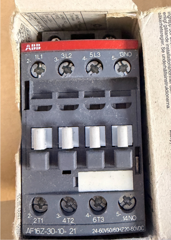

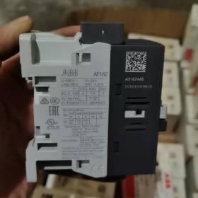
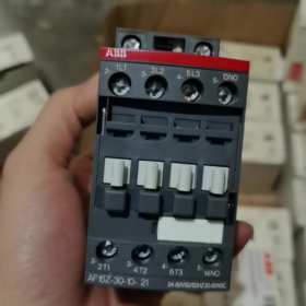
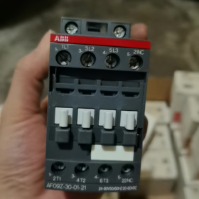
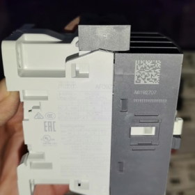
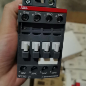
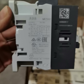
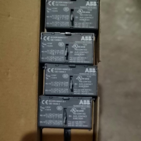
Pedido original de fábrica nº.: 1SBL176001R2110
- Definição de detalhamento do modelo
AF16Z 30 10 21
- AF16Z: Série AF; Z = Bobina eletrônica de ampla faixa de baixa potência (acionamento PLC direto capaz); Tamanho do quadro 16 aula
- 30: Principais contatos: 3 Normalmente aberto (3NÃO), sem contatos principais normalmente fechados
- 10: Contatos auxiliares integrados: 1 Normalmente aberto (1NÃO), 0 Normalmente fechado
- 21: Código da bobina → Tensão de controle: 24~60 V CA 50/60 Hz / 20~60V CC
⚠️ Diferença entre AF...Z e AF padrão: Consumo de energia da bobina extremamente baixo, suporta acionamento direto por saídas PLC DC24V, resistente a quedas de tensão (compatível com SEMI F47).
- Classificações elétricas principais
Tensão máxima do circuito principal: 690 V e
AC-1 (carga resistiva), ≤40°C ambiente: 30 UM
AC-3 (3-motor de fase, 400 V): 18 UM, adequado para 7.5 motor kW
AC-3 (690 V): 10.5 UM, máx.. 9 kW
Montagem: Montagem em trilho DIN, conexão de terminal de parafuso
Dimensões gerais: C 45 mm × H 86 mm × D 77 milímetros
Temperatura operacional: -40~+70°C (sem relé de sobrecarga térmica); -25~+60°C (com relé de sobrecarga térmica)
- Principais características da bobina
AC/DC universal de amplo alcance: CA 24~60V / CC 20~60V
Supressão de surto integrada; nenhum amortecedor RC externo ou diodo necessário
Baixo consumo de energia de retenção, ideal para operação energizada contínua
Suporta flutuações de tensão de curto prazo e quedas de tensão
- Identificação do Terminal
Circuito principal: 1L1-2T1, 3L2-4T2, 5L3-6T3
Contato auxiliar: 14NÃO (Normalmente aberto)
- Alternativas Comuns & Distinções
- AF16Z-30-10-11: Mesma faixa de tensão, equipado com bobina AF padrão (bobina Z de não baixa potência); não pode ser acionado diretamente por saídas PLC de baixa corrente, não intercambiável.
- AX16-30-10: Série econômica AX, sem bobina eletrônica de amplo alcance, tensão de controle fixa; não é possível substituir AF16Z.
- Para 1NO + 1Contatos auxiliares NC: Selecione o modelo AF16Z-30-11-21.
- Aplicações Típicas
Upstream de inversores de frequência variável, fãs & bombas de água, Equipamento HVAC, maquinaria de semicondutores, Controle de carga direto de saída PLC DC, locais industriais que exigem alta tolerância a flutuações de tensão.
ABB AF16Z-30-10-21 Contator Documento Técnico de Instalação
Pedido nº.: 1SBL176001R2110
- Instruções Gerais de Segurança
⚠️ Toda instalação, os trabalhos de fiação e manutenção devem ser realizados com toda a energia desconectada; procedimento de lockout-tagout é obrigatório. O trabalho deve ser realizado apenas por eletricistas qualificados.
- Classe de proteção: IP20. Somente para instalação em gabinete. Não instale ao ar livre, ambientes úmidos, locais com muita poeira ou exposição a gases corrosivos.
- Padrões aplicáveis: IEC/EN 60947-1, IEC/EN 60947-4-1; Certificado UL/CSA.
- AF16Z está equipado com uma bobina eletrônica de baixa potência e amplo alcance com circuito integrado de supressão de surtos. Não é necessário nenhum amortecedor RC externo ou conexão de diodo.
- Informações básicas do produto
2.1 Definição de modelo
AF16Z: Série AF, tamanho do quadro 16, Z = bobina eletrônica de baixa potência
30: 3 contatos principais normalmente abertos
10: Integrado 1 contato auxiliar normalmente aberto
21: Faixa de tensão da bobina CA 24 ~ 60 V 50/60 Hz / CC 20~60V
2.2 Dimensões Gerais
Largura 45 mm × Altura 86 mm × Profundidade 77 milímetros
2.3 Tabela de resumo de classificação
| Item | Parâmetro |
| Carga resistiva AC-1 (40 C) | 30 UM |
| Carga do motor AC-3 (400 V) | 18 UM, compatível com 7.5 kW motor trifásico |
| Tensão máxima de operação | 690 V e |
| Temperatura operacional (sem relé térmico) | -40 C ~ +70 C |
| Temperatura operacional (com relé de sobrecarga térmica) | -25 C ~ +60 C |
- Especificações de instalação mecânica
3.1 Métodos de montagem
Duas opções de montagem disponíveis:
- Montagem em trilho DIN (Recomendado)
Padrão ferroviário: TS35 (35×7,5mm / 35×15mm)
Operação: Prenda a trava inferior no trilho, pressione para baixo até que um clique audível confirme o travamento. Para remoção, use uma chave de fenda para forçar a trava inferior e levantá-la.
- Montagem do parafuso da placa base
Prenda na diagonal usando 2 × Parafusos M4; consulte o desenho de esboço para obter o espaçamento dos furos de montagem.
3.2 Orientação de montagem & Liberação
- Montagem vertical (terminais superiores & fundo) preferido. 90° a montagem lateral horizontal é permitida; a instalação invertida é proibida.
- Várias unidades podem ser montadas lado a lado sem redução de corrente. Mantenha espaço vertical ≥15 mm para ventilação; mantenha longe de componentes geradores de calor, como resistores e inversores.
- Evite instalação em locais com alta vibração. Aceleração de vibração >0.5g requer medidas de amortecimento de vibração.
- Especificações de fiação elétrica
4.1 Definição de marcação de terminal
Circuito principal superior: L1, L2, L3 (Entrada de energia)
Circuito principal inferior: T1, T2, T3 (Saída de carga)
Aplicações não-UL permitem alimentação de energia de cima ou de baixo; Instalações certificadas pela UL requerem entrada de energia dos terminais L superiores.
Terminais de bobina A1, A2: Entrada de sinal de controle (AC/DC não polarizado)
Contato auxiliar 13-14: Contato normalmente aberto integrado (1NÃO)
4.2 Especificação do cabo & Comprimento de decapagem
Comprimento padrão de decapagem de fio: 10 milímetros
Condutores do circuito principal: Cabo de cobre sólido/trançado 1~6 mm²; ponteiras recomendadas para cabos flexíveis
Controlar / condutores de circuito auxiliar: 0.75~2,5 mm²
4.3 Torque de aperto (Obrigatório)
Terminais do circuito principal: 1.5 N·m
Bobina A1/A2 & terminais de contato auxiliares: 1.2 N·m
Torque insuficiente causa superaquecimento do terminal; torque excessivo leva ao desgaste da rosca.
Ferramentas recomendadas: Chave de fenda PZ2 Pozidriv / 5.5 chave de fenda de torque plana mm.
- Notas críticas de aplicação de bobinas (Recurso principal do AF16Z)
- Faixa de tensão: AC24~60V / DC20~60V, ampla compatibilidade de tensão, acionamento direto por saídas PLC DC.
- Consumo de energia de retenção de bobina muito baixo, adequado para operação energizada de longo prazo; compatível com os requisitos de imunidade a queda de tensão SEMI F47.
- A1 e A2 não são polarizados; a polaridade não importa para o controle DC24V.
- Não aplique tensão de controle que exceda 60 V, caso contrário, o módulo da bobina eletrônica será destruído.
- Instalação de acessórios opcionais
- Contatos auxiliares montados na lateral (Série CA4)
Encaixe nas ranhuras laterais esquerda/direita sem ferramentas. Máximo 2 conjuntos de contatos auxiliares laterais podem ser instalados no AF16.
- Intertravamento mecânico
Instale para configuração de circuito reverso de dois contatores AF16Z para evitar fechamento simultâneo e curto-circuito entre as fases direta e reversa.
- Correspondência do relé de sobrecarga térmica
Compatível com relés térmicos da série TA25DU, montagem de encaixe direto embaixo do contator.
- Procedimento de comissionamento após ligar
- Em condição de desligamento: Inspeção visual para fiação correta, sem detritos metálicos, todos os terminais apertados com o torque especificado.
- Acione manualmente o mecanismo do contator para confirmar a operação suave sem emperrar.
- Teste o circuito de controle de forma independente: Aplique tensão de controle nominal em A1/A2; o contator deve puxar de forma confiável e sair suavemente após a remoção da energia.
- Verifique a comutação síncrona do contato auxiliar 13-14 com operação de contator.
- Conecte o circuito principal para teste sem carga; verifique se há ruído anormal e aumento rápido da temperatura terminal.
- 30-teste de operação carregado por minuto; verifique novamente a temperatura do terminal para garantir que o aumento da temperatura permaneça dentro dos limites permitidos.
- Falhas de instalação & Práticas Proibidas
❌ Operações proibidas:
Fios soltos expostos nos terminais do cabo
Apertando terminais enquanto energizados
Tensão de controle fora da faixa de 20~60 V
Bloqueio dos canais de ventilação acima e abaixo do contator
Instalação direta em ambientes com poeira combustível ou condensação contínua
Problemas comuns pós-instalação
- Contator vibrando/pull-in instável: Verifique se a tensão de controle está acima do nível operacional mínimo; verifique a queda de tensão ao longo dos cabos de controle.
- Superaquecimento dos terminais: Reaperte os terminais com o torque especificado; confirme se a seção transversal do condutor é adequada.
- Falha ao puxar quando acionado por PLC: Confirme se a unidade é AF16Z (bobina de baixa potência); bobina AF16 padrão não pode ser acionada diretamente por saídas de transistor PLC.
- Requisitos de manutenção
- Inspeção periódica da temperatura terminal e ruído anormal.
- Evite manobras repetidas acima da capacidade de interrupção nominal.
- Nunca opere o contator com a proteção de arco removida. Substitua a unidade completa quando os contatos sofrerem ablação severa.
Parâmetros de vida mecânica do ABB AF16Z-30-10-21
O AF16Z compartilha construção mecânica idêntica ao AF16 padrão. Dados técnicos oficiais:
✅ Resistência mecânica: 10 milhões de ciclos operacionais (10×10⁶ operações)
Condições de teste: Tensão nominal de controle, comutação sem carga, temperatura ambiente padrão.
Parâmetros-chave de suporte
- Frequência máxima de operação mecânica: 3,600 operações por hora
A operação contínua de alta frequência não deve exceder este limite para evitar desgaste mecânico acelerado.
- Resistência elétrica de referência (depende do tipo de carga, não é igual à vida mecânica)
AC-3 (400 Carga do motor V): Aprox.. 1,000,000 ciclos
AC-1 (carga resistiva): Aprox.. 1,600,000 ciclos
⚠️ A resistência mecânica representa o limite operacional mecânico; a vida útil em aplicações práticas é normalmente determinada pela erosão elétrica dos contatos.
Observações Suplementares
- AF16Z difere apenas por sua variante de bobina eletrônica de amplo alcance de baixa potência. Armadura, estrutura mecânica de ligação e contato são idênticas ao padrão AF16; as classificações de resistência mecânica permanecem inalteradas.
- A resistência mecânica real diminuirá em ambientes agressivos (poeira pesada, vibração contínua, alta temperatura).
- Definição de resistência mecânica: Ciclos de operação de pull-in/drop-out do contator acionados apenas pela bobina, sem carga conectada ao circuito principal.










NH42-63-318x560.png "Chaves de transferência automática tipo PC CHINT (ATS)NH42-63/4SZ")



