 Contator,disjuntor,sensor,Codificador,CLP,Conversor

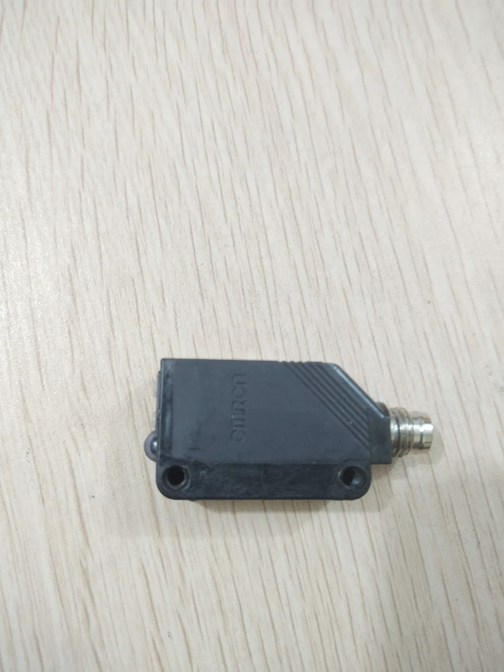

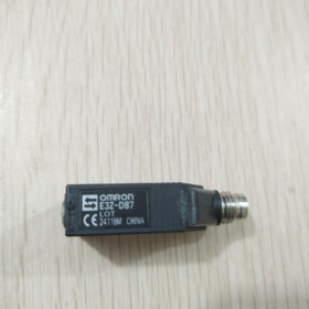
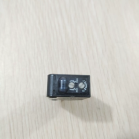
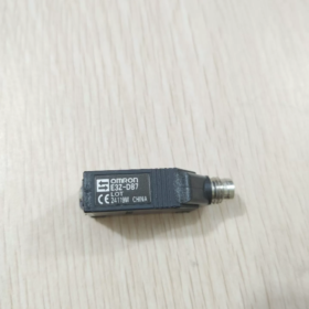
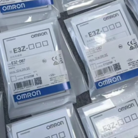
E3Z: Amplificador integrado compacto sensor fotoelétrico série
D: Detecção difusa reflexiva
8: Saída PNP (6 = saída NPN)
7: Conector M84 pinos, tipo reflexivo difuso de longo alcance (2 = tipo de cabo)
Especificações Técnicas Principais
| Item | Especificação |
| Método de detecção | Difuso-reflexivo |
| Fonte de luz | LED infravermelho, 870 nm |
| Distância de detecção padrão | 1000 milímetros (300× papel branco de 300 mm) |
| Saída | Saída de transistor PNP, máx.. carregar 100mA |
| Modo de operação | Luz acesa / Dark-ON selecionável (Interruptor DIP L/D) |
| Fonte de energia | CC 12‑24 V ±10% |
| Tempo de resposta | ≤1ms (agir / reiniciar) |
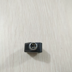
| Conexão | Conector macho M8 de 4 pinos; cabos de acoplamento: XS3F‑M421‑402‑A (2 sou hetero), XS3F‑M422‑402‑A (2 m angulado) |
| Proteção de entrada | IP67 |
| Material da Habitação | Plástico de engenharia PBT |
| Temperatura operacional | -25°C ~ +55°C (sem gelo ou condensação) |
| Funções de proteção | Proteção contra polaridade reversa, proteção contra curto-circuito de saída, resistência à interferência mútua |
| Indicadores | Laranja: Indicador de operação; Verde: Indicador de estabilidade |
Pinagem M84pin (Conector macho do lado do sensor)
- Marrom: CC24V+
- Branco: Seleção de modo (LONDRES)
- Azul: 0V GND
- Preto: Saída de sinal PNP
Interruptor L = Luz LIGADA (a saída é LIGADA quando o objeto se aproxima); Interruptor D = Escuro LIGADO (a saída é LIGADA sem nenhum objeto). Potenciômetro de volta única na lateral ajusta a sensibilidade.
Guia de seleção de séries relacionadas
- E3ZD67: Função idêntica & distância de detecção, Saída NPN, Conector M8 (Contraparte NPN do D87)
- E3ZD82: PNP, 1 m difusoreflexivo, 2 m cabo pré-cabeado fixo, sem conector
- E3ZD87IL3: Versão habilitada para IOLink; parâmetros de hardware idênticos
Aplicações Típicas
Detecção de presença de objeto em linhas transportadoras, detecção de posição, contagem de peças, máquinas de embalagem. Adequado para identificação de alvos até 1m. O desempenho reflexivo difuso é afetado pela cor do objeto / refletividade; a distância efetiva diminui significativamente para alvos de cores escuras.
Instalação & Notas de comissionamento
- Evite fundos altamente reflexivos; mantenha os fundos bem longe do alcance máximo de detecção do sensor.
- Ajuste o potenciômetro até que o indicador verde de estabilidade permaneça LIGADO, indicando margem de detecção suficiente.
- Quando vários sensores são montados lado a lado, compensar seus ângulos para evitar interferência óptica mútua.
- Garanta a vedação do conector M8 contra contaminação por água e óleo.
OMRON Tabela de pesquisa de falhas E3ZD87
Recapitulação dos alfinetes: 1 Marrom DC24V+|2 Branco Modo LON/DON|3 Azul 0V|4 Saída PNP preta
Definição do indicador: Verde = indicador de estabilidade; Laranja = Indicador de operação. O LED infravermelho é invisível aos olhos humanos – não procure luz vermelha visível.
| Sintoma de falha | Possíveis causas | Ação de solução de problemas |
| Ligar: ambos os indicadores verde e laranja desligados | 1. Sem tensão de alimentação / tensão insuficiente | 1. Meça a tensão entre o pino 1-3 no conector do sensor: deve ser DC12‑24V |
| 2. Polaridade de energia reversa | 2. Troque fios marrons e azuis | |
| 3. Oxidado / loose M8 pins, cabo quebrado | 3. Test with a known‑good M8 cable | |
| 4. Internal power circuit damage (sobretensão / water ingress) | 4. If still no indicators after cable replacement → sensor defective, substituir unidade | |
| Green indicator stays ON; orange indicator never changes with/without target | 1. Target beyond sensing range | 1. Reduce sensing distance; turn potentiometer clockwise for higher sensitivity |
| 2. Sensitivity potentiometer set too low | 2. Toggle L/D switch | |
| 3. Wrong L‑ON/D‑ON switch setting | 3. Remove nearby reflective background surfaces | |
| 4. Poor reflectivity of dark target | 4. Dark‑colored objects yield much shorter effective range | |
| 5. Interference from reflective background | ||
| Orange indicator lights, but PLC receives no signal | 1. Incorrect PNP output wiring; black pin 4 not connected to PLC input | 1. Confirm PLC input module type for PNP logic |
| 2. Wrong PLC input common‑terminal wiring (PNP requires PLC input common tied to 0 V) | 2. Verify black‑wire loop; do not leave floating | |
| 3. Output load exceeds 100 mA rating | 3. Locate short‑to‑ground fault; power‑cycle to clear protection | |
| 4. Output short‑circuit protection triggered | ||
| Indicators flicker; unstable detection, false triggering without target | 1. Optical crosstalk between adjacent photoelectric sensors | 1. Angle sensors away from one another |
| 2. Uneven surface reflectivity of target | 2. Turn potentiometer counter‑clockwise to lower sensitivity | |
| 3. Excess sensitivity picking‑up background reflection | 3. Route cables away from power lines; clean lens window | |
| 4. Power‑supply fluctuation; cable routed alongside power cables | 4. Check 24 V power‑supply ripple | |
| 5. Pó / oil contamination on lens window | ||
| Green indicator OFF; only orange indicator ON | Insufficient sensing margin, operando perto do limite de detecção, instável em condições de campo | Aumente a sensibilidade ou reduza a distância de detecção. A operação confiável requer indicador verde estável. |
| Funciona normalmente após ligar, falha após o tempo de execução; recupera quando resfriado | 1. Temperatura ambiente muito alta | 1. Confirme a temperatura ambiente entre -25~+55℃ |
| 2. Grande queda de tensão na alimentação de 24 V sob carga | 2. Meça a tensão real no sensor sob condição carregada | |
| 3. Envelhecimento do sensor interno | 3. Se a falha ocorrer de forma consistente, substituir sensor |
Teste de bancada rápido padrão (Verifique a integridade do hardware do sensor)
- Use um cabo M8 em boas condições: pino 1 Marrom para 24V+, pino3 Azul para 24V; deixe o pino 2 branco e o pino 4 preto completamente desconectados (flutuante).
- Aplicar energia: O indicador de estabilidade verde deve acender.
✅ Verde LIGADO: Hardware do sensor OK. A falha está na fiação de campo, Lógica CLP, cabeamento ou ambiente de montagem.
❌ Green OFF: Sensor internally damaged; substituir sensor.
Notas importantes
- E3ZD87 is PNP output. Do not treat as NPN, otherwise indicators work but PLC receives no signal.
- Pin 2 White floating = default LightON; shortto0V selects DarkON. Do NOT connect pin 2 to 24V+.
- Greenindicator OFF means insufficient sensing margin. Even if orange indicator toggles, field falsetrigger risk is high. Always commission for steadyON green indicator.
OMRON E3ZD87: How to Judge Exceeded Sensing Range
Nominal rating: 1000 mm maximum with 300×300 mm white paper. Effective range reduces sharply for lowreflectivity darkcolored targets.
Definição do indicador: Green = stability margin indicator; Orange = operation output indicator
Método 1: Indicatorbased check (fieldfriendly, no tape measure)
- Turn sensitivity potentiometer fully clockwise for maximum sensitivity.
- Mova o alvo real em direção ao sensor começando de uma distância distante.
CasoA: O indicador de operação laranja acende, mas o indicador de estabilidade verde nunca acende
👉 Operando além da faixa utilizável confiável. A detecção é marginal; vibração, poeira ou deslocamento menor do alvo podem causar perda de sinal. Não use a esta distância.
Caso B: Abordagens alvo; indicador laranja LIGADO E indicador de estabilidade verde permanece LIGADO
👉 Dentro da faixa de trabalho válida com margem de detecção adequada. Aceitável para operação.
✔ Regra de comissionamento: Na posição de trabalho, o indicador verde deve permanecer continuamente LIGADO. LaranjaON / verdeOFF = marginal / condição de sobrefaixa.
Método 2: Teste de distância (usando alvo de referência de white paper)
- Use alvo de papel branco de 300×300mm; potenciômetro ajustado para sensibilidade máxima.
- Aumente gradualmente a distância entre o sensor e o papel:
1000 milímetros: Nenhuma detecção de alvo, independentemente do ajuste do potenciômetro; o indicador laranja permanece desligado → além da faixa nominal.
8001000 zona mm: Possível cintilação laranja intermitente, indicador verde DESLIGADO. Esta é a zona marginal; evitar para implantação de engenharia.
Recomendação prática de engenharia: Mantenha a distância real de trabalho de 0700 mm para preservar a margem de segurança.
Método 3: Distinguir o verdadeiro overrange e a baixa refletividade do alvo
Sensores reflexivos difusos não possuem distância de corte fixa. A cor do alvo altera a distância de detecção efetiva.
Livro branco: aprox.. 1000 mm máx.
Peça cinza: aprox.. 500700 milímetros
Borracha preta / peça fosca escura: a distância efetiva pode cair para apenas 200-400 mm
Teste rápido de discriminação: Coloque papel branco na sua lacuna de trabalho.
① O white paper aciona o greenON; peça real NÃO → Hardware do sensor bem; baixa refletividade do alvo cria overrange eficaz. Reduza a distância de montagem.
② O papel branco também não acende em verde → A lacuna física excede a capacidade do sensor.
Cenários comuns de diagnóstico incorreto
- Fundo reflexivo (parede / metal atrás do alvo): O indicador verde permanece LIGADO devido ao reflexo do fundo, mas a peça real não pode ser detectada.
👉 Remédio: Aumente a distância entre a peça de trabalho e o fundo, ou reduzir a sensibilidade.
- Potenciômetro muito baixo: A distância física é aceitável, mas o indicador verde permanece DESLIGADO.
👉 Antes da avaliação da faixa, sempre gire o potenciômetro totalmente no sentido horário para sensibilidade máxima.
Procedimento passo a passo de avaliação de campo
- Potenciômetro ajustado para sensibilidade máxima; definido para o modo LightON; clean lens window.
- Coloque a peça de trabalho real na posição operacional pretendida.
- Observe os indicadores:
✅ Verde + Laranja ambos LIGADOS → Distância aceitável
❌ Apenas Laranja LIGADO, Verde DESLIGADO → Marginal / ultrapassar a faixa; deve reduzir a lacuna de instalação
❌ Laranja nunca é ativado → Gap excede a capacidade de detecção do sensor
Observação: Este sensor não possui leitura numérica de distância. O intervalo só pode ser avaliado através do status do indicador. A variante IOLink E3ZD87IL3 fornece valores quantitativos de intensidade de sinal.
Fatores que afetam a distância de detecção do sensor fotoelétrico difusoreflexivo OMRON E3ZD87
Nominal 1000mm é especificado sob condições de referência: 300× papel branco de 300 mm, sensibilidade máxima, sem interferência de fundo. A distância efetiva do mundo real é afetada por vários fatores abaixo.
- Propriedades do objeto de destino (Fator dominante)
- Cor & refletividade
Branco / com luz brilhantecolorido: Alta reflexão, perto de 1000 mm nominais
Cinza: Distância efetiva reduzida
Preto, fosco escuro, borracha: Reflexão infravermelha fraca; a distância efetiva pode cair para 200.400 mm
- Tamanho alvo
Alvos menores que o ponto do sensor retornam menos luz; a distância máxima utilizável diminui. A detecção pode falhar completamente se o alvo for menor que o tamanho do ponto.
O alvo do teste de referência é papel branco de 300×300mm. Peças pequenas sofrem redução de alcance.
- Material de superfície & textura
Superfícies espelhadas polidas: A luz refletida pode perder a janela do receptor, causando detecção instável.
Superfícies difusas ásperas: Bom desempenho de detecção.
Translúcido / objetos transparentes: O infravermelho passa; sinal de retorno enfraquece, alcance cai fortemente.
- Ângulo de incidente
Se a superfície alvo não for aproximadamente perpendicular ao eixo óptico do sensor, a luz refletida é desviada e o alcance efetivo diminui. Monte de forma que o alvo fique voltado para o sensor aproximadamente diretamente.
- Configurações do sensor & Doença
- Potenciômetro de sensibilidade
Sentido horário = maior distância máxima de detecção; sentido anti-horário = distância máxima de detecção mais curta.
Não execute com sensibilidade máxima na produção, risco de captar reflexos de fundo. Sempre aponte para o indicador de estabilidade verde estável.
- Contaminação de lentes
Pó, fluido de corte, névoa de óleo, película de água na lente atenua a intensidade da luz, encurtar a distância de detecção e acionar falsa detecção. Mantenha a limpeza das lentes.
- Ambiente & Condições de fundo
- Fundo reflexivo atrás do alvo
Painéis metálicos, paredes brancas atrás do alvo podem ser detectadas em vez da peça de trabalho. O sensor parece ter longo alcance, mas não consegue detectar peças reais.
Remédio: Aumente a separação entre a peça de trabalho e o fundo, ou menor sensibilidade.
- Crosstalk óptico entre sensores adjacentes
Múltiplas unidades E3Z montadas próximas podem interferir opticamente, causando leituras erráticas e desempenho de faixa anômalo. Ângulos e espaçamento de montagem deslocados.
- Luz ambiente forte
A luz solar direta ou luz incandescente brilhante atingindo a janela do receptor sobrecarrega o sinal infravermelho, encurtando o alcance utilizável ou causando falha de detecção. Prevenir a incidência direta de luz forte.
- Elétrica & Influências das condições operacionais
- Tensão de alimentação
A alimentação abaixo de 12 V reduz a potência de saída do LED infravermelho e encurta o alcance de detecção. Meça a tensão no conector M8 do sensor, não apenas no gabinete da fonte de alimentação.
- Temperatura ambiente
No limite superior de temperatura perto de +55℃, A eficiência luminosa do LED cai, reduzindo ligeiramente o alcance máximo de detecção. Baixa temperatura até 25°C tem impacto menor.
- Queda de tensão no cabo
Cabos M8 longos criam queda de tensão, diminuindo indiretamente a unidade de LED e reduzindo o alcance efetivo.
Diretrizes Práticas de Engenharia
- Nominal 1000 mm é a condição ideal de laboratório. Não projete projetos em torno da classificação completa de 1000 mm.
Alvos claros: Recomendar folga operacional ≤700mm
Escuro / alvos negros: Recomendar folga operacional ≤400mm
- Julgue a usabilidade pelo status do indicador, não folha de dados distância nominal: O indicador verde deve permanecer LIGADO na posição de trabalho. LaranjaON / greenOFF = margem marginal insuficiente.
Diferenciação rápida de falhas
O white paper aciona o greenON na posição de trabalho; peça de trabalho real NÃO → Excesso de alcance efetivo devido à baixa refletividade do alvo.
Mesmo o papel branco não acende o indicador verde → A lacuna física excede a capacidade do sensor, ou sujeira nas lentes / tensão de alimentação insuficiente.





NH42-63-318x560.png "Chaves de transferência automática tipo PC CHINT (ATS)NH42-63/4SZ")



