 Contator,disjuntor,inversor solar,medidor elétrico,baterias solares

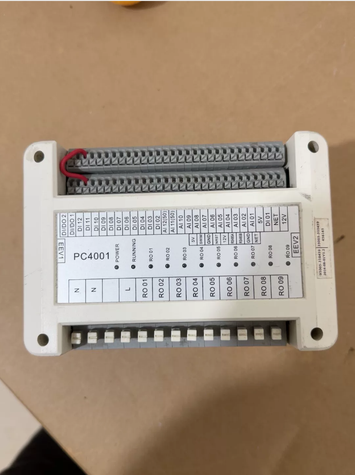

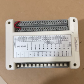
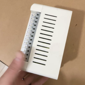
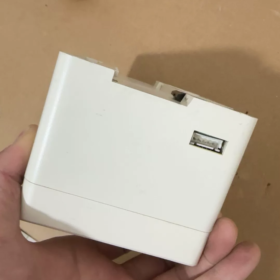

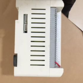
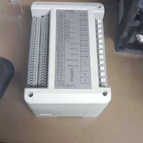
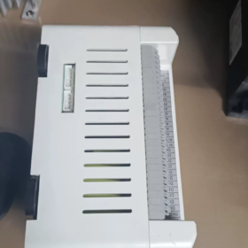
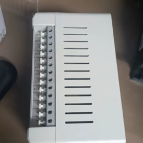
PHNIX PC4001
PHNIX PC4001 is a main controller / control board designed for equipment including air-to-water heat pumps, condicionadores de ar centrais, industrial water chillers, and printing machines. It is a dedicated embedded main control board proprietary to PHNIX, commonly used in commercial heat pumps and industrial refrigeration units.
- Informações Básicas
Marca: PHNIX
Modelo: PC4001
Tipo: Main controller (control board) for heat pump / refrigeration units
Equipamento aplicável:
PHNIX commercial air-to-water heat pumps (hot water / heating / ultra-low temperature Polaris series)
Industrial water chillers / refrigeration units
Printing machines, condicionadores de ar centrais, pool heat pumps
Nature: Dedicated main control board with pre-programmed firmware, not a general-purpose PLC.
- Principais Funções (Heat Pump / Refrigeration Control)
- Multi-mode Control
Heating / Resfriamento / Hot Water / Constant Temperature Dehumidification
- Temperature Control
Closed-loop control of supply and return water temperature
Monitoring of ambient temperature, discharge temperature, and coil temperature
- Funções de proteção
High pressure, low pressure, sobrecarga, perda de fase, phase sequence, anti-freeze, high discharge temperature
Sensor fault, flow switch, and compressor protection
- Compressor Management
Sequencing, time delay, and balanced start/stop for 1-3 compressores
- External Device Control
Four-way valve, electronic expansion valve, fan, water pump, electric heater
- Comunicação & Display
Supports wired controller (Modelo 95005 série)
Some versions support Modbus-RTU
- Typical Hardware Specifications
Fonte de energia: AC 220V ±15% / 380V
Inputs:
NTC 10KΩ temperature sensors (multiple)
High pressure switch, low pressure switch, flow switch, phase sequence protector
Resultados (Relé / Thyristor):
1-3 compressor outputs
Four-way valve, fan, water pump, electric heater, alarm
Display: Onboard LED run/fault indicators
Controller Interface: Dedicated 4/5-pin connector (for Model 95005, etc.)
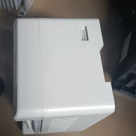
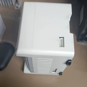
Dimensões: Standard PCB board (aprox.. 150×120mm)
Montagem: Screw-mounted inside the unit cabinet
- Common Replacement / Compatible Models
PC4001: Basic universal version
430084: Common PHNIX heat pump mainboard (same-platform replacement)
20000-430084: Extended part number for ordering
PC4002 / PC4003: Upgraded versions (more compressors / enhanced protection)
- Códigos de falha comuns
E1: High pressure protection
E2: Low pressure protection
E3: Supply water temperature sensor fault
E4: Return water temperature sensor fault
E5: Sobrecarga / sobrecorrente
E6: Phase sequence error / perda de fase
E7: Anti-freeze protection
E8: Excessively high discharge temperature
- Difference from Carlo Gavazzi PC4001
Carlo Gavazzi PC4001: Phase sequence / phase loss protection relay (electrical protection)
PHNIX PC4001: Main control board for complete heat pump system (system control)
The two are completely different and not interchangeable.
- Pedido & Manutenção
Original Ordering: Through PHNIX distributors (mostly using extended part number: 20000-430084)
Manutenção: Requires original factory firmware; board replacement is generally the only solution.
PHNIX PC4001 Mainboard: Complete Installation & Commissioning Manual
The PC4001 is a dedicated main control board for PHNIX commercial heat pumps / water chillers (not a general-purpose relay). Below is the factory-level full procedure for installation, fiação, power-on, parameter setting, and troubleshooting (applicable to ultra-low temperature heat pumps, aquecedores de água, refrigeradores, and printing machine units).
- Preparação de pré-instalação
1.1 Confirmação do modelo & Compatibilidade
Mainboard: PC4001 / 20000-430084 (extended part number)
Aplicativo: PHNIX 3-25HP commercial heat pumps / water chillers (single / dual compressor)
Wired controller: Matching Model 95005 wired controller (4/5-core cable)
Fonte de energia: Three-phase AC 380V / Single-phase AC 220V (depending on unit)
1.2 Ferramentas & Acessórios
chave Phillips, descascador de fios, multímetro, voltage tester
Crimp terminals, cable ties, fita isolante
NTC 10KΩ temperature sensors (supply water / return water / discharge / ambient / bobina)
Phase sequence protector (PC4001 has built-in phase loss / phase sequence protection)
1.3 Precauções de segurança
Install with power disconnected: Turn off main power and attach lockout tag
Anti-static: Touch grounded metal to discharge static; do not operate with wet hands
Separate strong and weak current: Route power / compressor cables separately from signal wires
- Instalação Mecânica (Mainboard Mounting)
- Mounting Location: Inside the unit’s electrical cabinet, away from compressors, fãs, and high-temperature areas
- Fixação: Secure the PCB with 4 M3 screws (do not overtighten to avoid cracking the PCB)
- Orientation: Mount vertically for heat dissipation; keep away from water accumulation / condensation
- Clearance: Leave ≥3cm ventilation space around the board
- Standard Wiring (PC4001 Terminal Definitions)
3.1 Power Input (Trifásico 380V)
L1, L2, L3: Three-phase power input (correct phase sequence)
N: Neutral wire
Educação Física: Terra protetora (must be connected for shock and interference protection)
3.2 Compressor Outputs (1-2 unidades)
COMP1: Compressor 1 (fio vivo)
COMP2: Compressor 2 (fio vivo)
COM: Common neutral
OVL: Proteção contra sobrecarga (series-connected normally closed thermal relay)
3.3 External Device Control
FV: Four-way valve (heating / cooling switching)
FAN: Condensing fan
PUMP: Bomba de água / flow switch
EH: Electric heater (opcional)
ALARM: Fault alarm output (dry contact)
3.4 Temperature Sensors (NTC 10KΩ)
T1: Supply water temperature (obrigatório)
T2: Return water temperature (obrigatório)
T3: Discharge temperature (obrigatório)
T4: Temperatura ambiente
T5: Coil temperature
3.5 Protection Switches (Normally Closed Inputs)
HP: High pressure switch (obrigatório)
LP: Low pressure switch (obrigatório)
FLOW: Flow switch (obrigatório)
PH: Phase sequence / perda de fase (embutido, can be connected externally in series)
3.6 Wired Controller Interface
CN5 / CN6: 4-core cable (VCC, GND, DATA, CLK)
Cable length: ≤15 meters, shielded cable, kept away from high-voltage lines
3.7 Wiring Guidelines
All terminals use crimp terminals + tinning to prevent loosening
Route strong and weak current in separate ducts; shield of signal cables grounded at one end
Compressor wires ≥2.5mm², signal wires 0.75mm²
Secure wiring with cable ties to avoid abrasion by fans or compressors
- Pre-power Inspection (Critical)
- Multimeter Checks:
L1-L2-L3: Balanced three-phase voltage (380V±5%)
Insulation: Compressor / fan insulation to ground ≥ 2MΩ
- Phase Sequence Check:
Use phase sequence meter to confirm L1-L2-L3 is positive phase sequence
Incorrect phase sequence triggers E6 on PC4001
- Sensor Check:
All NTC sensors measure approx. 10KΩ at room temperature
No short circuit or open circuit in sensor cables
- Protection Switches:
High pressure / low pressure / flow switches are normally closed and conducting
No bypassed protections (do NOT short HP / LP / FLOW)
- Power-on Commissioning (Wired Controller Operation)
5.1 First Power-on
Turn on main power → Mainboard LED lights up, wired controller shows boot screen
Self-test: 30 segundos, checking sensors, inputs/outputs, and protections
5.2 Unit Parameter Setting (Required)
To enter parameters: Long press [DEFINIR] on wired controller for 5 seconds → Password [6666]
P00: Unit type selection
0: Heat pump water heater
1: Heat & cool heat pump
2: Industrial water chiller
P01: Number of compressors (1/2)
P02: Rated supply water temperature (hot water 55℃ / chiller 7℃)
P03: Temperature differential (2-3℃)
P04: Anti-freeze temperature (5℃)
P05: High discharge temperature protection (110-120℃)
P06: Fan control (0: constant run / 1: thermostatic control)
P07: Water pump control (0: unit interlock / 1: constant run)
5.3 Calibration & Testing
- Temperature Calibration:
Compare multimeter readings with controller display → Calibrate in P20-P24
- Manual Test (Service Mode):
Long press [MODE + OK] para 5 seconds → Manual output mode
Test sequentially: COMP1, COMP2, FV, FAN, PUMP, ALARM
Verify normal pull-in, no short circuit, no abnormal odor
5.4 Phase Sequence & Protection Test
Disconnect any phase → Immediate E6 (perda de fase)
Reverse phase sequence → E6 (phase sequence error)
Open high pressure switch → E1 (high pressure)
Disconnect supply water sensor → E3 (sensor fault)
- Operational Commissioning
- Mode Selection: Hot Water / Resfriamento / Heating
- Temperature Setting:
Hot water: 50-55℃
Chilled water: 7-12℃
Heating: 45-55℃
- Monitoramento:
Compressor starts after 3-minute delay (prevents frequent cycling)
Discharge temperature 60-90℃ (≤110℃)
Pressure levels:
Resfriamento: High pressure 12-18bar, low pressure 3-5bar
Heating: High pressure 18-25bar, low pressure 1.5-3bar
- Protection Operation:
Over-temperature / over-pressure → immediate shutdown with corresponding fault code
Fault lockout: Reset by power cycle or controller [Reset]
- Códigos de falha comuns & Soluções
E1: High pressure protection → Check dirty condenser, fan, high pressure switch
E2: Low pressure protection → Check insufficient refrigerant, vazamento, low pressure switch
E3: Supply water sensor fault → Check T1 wiring, damaged sensor
E4: Return water sensor fault → Check T2
E5: Sobrecarga / overcurrent → Check compressor, relé térmico, tensão
E6: Phase sequence / phase loss → Correct phase sequence, check three-phase input
E7: Anti-freeze protection → Check water temperature, pump, anti-freeze settings
E8: High discharge temperature → Check refrigerant, heat dissipation, discharge sensor
- Key Difference from Carlo Gavazzi PC4001
PHNIX PC4001: Complete heat pump main control board (controlar + proteção)
Carlo Gavazzi PC4001: Phase sequence relay (only phase loss / phase sequence protection)
Not interchangeable
- Delivery List
PC4001 mainboard
Manual / parameter sheet
Wired controller (95005)
Sensors (T1/T2/T3)
Terminal kit
PHNIX PC4001 Complete Parameter Setting Manual (Using 95005 Controller)
The PC4001 is matched with the Model 95005 wired controller; all parameters are set via the controller.
Core steps: Long press SET 5s → Password 6666 → Select P parameter → Modify → Save
- Entering Parameter Settings (Essential Steps)
1.1 Enter Menu
Controller on normal standby screen
Long press [DEFINIR] key for 5 segundos
Display shows P00, enter password: 6666
Press [OK] to enter parameter list
1.2 Button Functions
[DEFINIR]: Confirm, enter, up / +
[C/F]: Down / -, switch
[MODE]: Exit, back
[OK]: Save, lock
1.3 Parameter Editing Flow
- Press [DEFINIR / C/F] to select parameter (P00-P30)
- Press [DEFINIR + C/F] together → value flashes
- Press [DEFINIR / C/F] to adjust value
- Press [DEFINIR + C/F] together again → save (stops flashing)
- Long press [MODE] para 3 seconds → exit menu
- Core Basic Parameters (P00-P09, Required)
P00 Unit Type (Most Important)
0: Heat pump water heater (padrão)
1: Heat & cool heat pump
2: Industrial water chiller
P01 Number of Compressors
1: 1 compressor
2: 2 compressores
P02 Rated Set Temperature
Hot water: 50-55℃
Heating: 45-55℃
Chilled water: 7-12℃
P03 Temperature Differential (On/Off Offset)
Recomendado: 2-3℃
Exemplo: Set 55℃, stop at 57℃, start at 54℃
P04 Anti-freeze Temperature
Default: 5℃
Water temp <5℃ → auto start pump / low-temp heating
P05 High Discharge Temperature Protection
Default: 110℃
Recomendado: 105-115℃ (immediate shutdown if exceeded)
P06 Fan Control Mode
0: Constant run (always on in cooling / heating)
1: Thermostatic control (stops at set temp, restarts low)
P07 Pump Control Mode
0: Unit interlock (pump runs when compressor runs)
1: Constant run (runs continuously when powered)
P08 Compressor Time Delay Protection
Default: 3 minutos
Range: 0-5 minutos (prevents frequent starting)
P09 Current Protection (Sobrecarga)
Set to compressor rated current × 1.1-1.2
Overcurrent → E5 overload protection
- Temperature Calibration Parameters (P20-P24)
P20 Supply Water Temp (T1) Calibration
Actual temperature – Displayed temperature = Calibration value
Exemplo: Actual 50℃, display 52℃ → set -2
P21 Return Water Temp (T2) Calibration
P22 Discharge Temp (T3) Calibration
P23 Ambient Temp (T4) Calibration
P24 Coil Temp (T5) Calibration
Range: -10~+10℃
Must save and exit after calibration
- Proteção & Advanced Parameters (P25-P30)
P25 High Pressure Protection Value
Resfriamento: 20-22 bar
Heating: 25-28 bar
P26 Low Pressure Protection Value
Resfriamento: 1.5-2 bar
Heating: 1.0-1.5 bar
P27 Defrost Temperature / Time
Defrost start: -3~-5℃
Max defrost duration: 10 minutos
P28 Electric Heating Enable Temperature
Exemplo: ≤40℃ allows electric heater activation
P29 Modbus Address (Opcional)
Default: 1
Set to 1, 2, 3… for multi-unit networking
P30 Restore Factory Defaults
0: Do not restore
1: Restore defaults (use with caution)
- Manual Test Mode (For Service)
Enter Manual Test
Normal screen → Long press [MODE + OK] para 5 segundos
Display shows TEST
Manual Output Test
Press [DEFINIR / C/F] to select output:
- COMP1: Compressor 1
- COMP2: Compressor 2
- FV: Four-way valve
- FAN: Fan
- PUMP: Bomba de água
- ALARM: Alarm
Press [OK] to switch on/off
Long press [MODE] to exit test
- Falhas Comuns & Parameter Adjustments
E1 High Pressure: Increase P25 by 1-2 bar or clean condenser
E2 Low Pressure: Decrease P26 by 0.5 bar or recharge refrigerant
E3/E4 Sensor Fault: Calibrate P20/P21 or replace NTC 10K
E6 Phase Sequence: Swap any two of L1/L2/L3
Frequent Cycling: Increase P03 differential to 3-5℃
E8 High Discharge Temp: Set P05 to 110℃ or check cooling
- Quick Parameter Setting Table (Direct Input)
| Param | Water Heater | Heat & Cool | Chiller |
| P00 | 0 | 1 | 2 |
| P01 | 1-2 | 1-21-2 | |
| P02 | 53℃ | 50℃ | 7℃ |
| P03 | 3℃ | 3℃ | 2℃ |
| P04 | 5℃ | 5℃ | 4℃ |
| P05 | 110℃ | 110℃ | 105℃ |
| P06 | 1 | 0 | 1 |
| P07 | 0 | 0 | 1 |
| P08 | 3min | 3min | 3min |
- Notas
Parameters must be saved after editing (value stops flashing)
Do NOT short protection terminals (HP/LP/FLOW)
Use precision multimeter for temperature calibration
Lock parameters after commissioning: Change password to 8888 to prevent accidental changes


")

 product and is currently discontinued. The official direct replacement is the 3rd generation model 750-377.")


")

NH42-63-318x560.png "Chaves de transferência automática tipo PC CHINT (ATS)NH42-63/4SZ")


