 Contator,disjuntor,sensor,Codificador,CLP,Conversor


- Interpretação do modelo
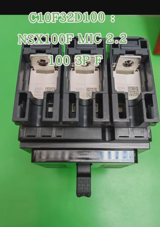
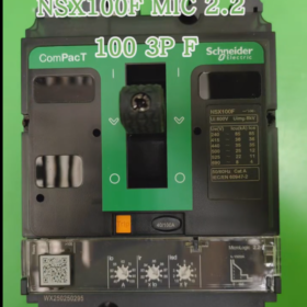
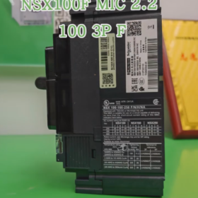
C10F32D100 is the complete order code of Schneider’s new-generation ComPacT NSX series disjuntores em caixa moldada. The meaning of each segment is as follows:
| Segmento de código | Significado | Descrição |
| C10 | Frame Size and Breaking Capacity | C10 = NSX100F, frame current 100A, breaking capacity Class F (36kA@415VAC) |
| F | Classe de Capacidade de Quebra | F = 36kA@415VAC, suitable for standard industrial applications |
| 3 | Número de poloneses | 3 = 3-pole (3P3D, sistema trifásico de três fios) |
| 2D | Tipo de unidade de viagem | 2D = MicroLogic 2.2 electronic trip unit with display function |
| 100 | Corrente nominal | 100UM, adjustable range 90-100A |
- Parâmetros técnicos principais
Parâmetros Básicos
| Parâmetro | Valor | Descrição |
| Tipo de produto | Disjuntor em caixa moldada (MCCB) | New-generation ComPacT NSX100F |
| Tensão nominal | 690VAC/50-60Hz | Tensão máxima de operação |
| Corrente nominal (Eu) | 100UM | Corrente operacional contínua |
| Capacidade de ruptura final (UTI) | 36kA@415VAC | Capacidade máxima de interrupção |
| Capacidade de interrupção de serviço (CIs) | 36kA@415VAC (100%) | Capacidade de interrupção de serviço |
| Tipo de montagem | Fixo | Montagem padrão, tipo de plug-in opcional (C10F32D100P) |
| Protection Category | Categoria A | Em conformidade com IEC 60947-2 padrão |
MicroLógica 2.2 Trip Unit Parameters
| Função de proteção | Característica | Faixa ajustável |
| Long-time Delay Protection (eu) | Proteção contra sobrecarga, inverse time-lag | 0.8-1.0脳Iu (90-100UM) |
| Short-time Delay Protection (S) | Proteção contra curto-circuito, definite time-lag | 3-6脳Iu, ajustável |
| Instantaneous Protection (EU) | Short-circuit instantaneous tripping, fixo | 10脳Iu (1000UM) |
| Função de exibição | Current measurement and status indication | Real-time display of three-phase current |
Physical and Electrical Characteristics
| Parâmetro | Valor |
| Perda de energia | 14.1C |
| Peso | Approximately 2.5kg |
| Padrões de Conformidade | CEI 60947-2, GB 14048.2 |
| Certificações | CE, CCC, RoHS |
III. Recursos funcionais
- Proteção Abrangente: Provides three-stage protection including long-time delay, short-time delay and instantaneous protection, effectively preventing overload and short-circuit faults.
- Controle Preciso: Compared with thermal-magnetic trip units (TM series), electronic trip units offer more accurate protection curves and adjustable parameters.
- Visualização de status: MicroLógica 2.2 is equipped with LED display for real-time monitoring of current and fault status.
- Projeto Modular: Supports a variety of accessories (contatos auxiliares, contatos de alarme, liberação de subtensão, etc.) for flexible installation.
- Environmental Friendly: Schneider Green Signature design, reducing energy consumption and carbon footprint.
- Operação fácil: Ergonomic handle for labor-saving operation; front-mounted accessories reduce wiring time by 40%.
- Cenários de aplicação
- Sistemas de distribuição de energia industrial: Used as main switch or branch switch to protect motors, transformers and distribution lines.
- Construindo Sistemas Elétricos: Low-voltage distribution cabinets in commercial buildings and industrial plants.
- Centros de controle de motores (MCC): Protect three-phase motors from locked rotor and overload conditions.
- Centros de dados: Power protection for critical loads to ensure power supply continuity.
- New Energy Sector: DC-side protection of photovoltaic inverters and energy storage systems (additional configuration required).
- Product Comparison
Comparison with Trip Units of the Same Series
| Modelo | Tipo de unidade de viagem | Principais diferenças | Cenários de aplicação |
| C10F32D100 | MicroLógica 2.2 | Electronic trip unit with display, proteção de três estágios | Industrial applications requiring precise protection and monitoring |
| C10F3TM100 | TM100D Thermal-Magnetic Trip | Unidade de disparo termomagnético, proteção em dois estágios, econômico | Simple power distribution without precise adjustment requirements |
| C10F33D100 | MicroLógica 3.2 | Adicionada proteção contra falha à terra (30-3000mA) |
Comparison with Chint Alternative Models
| Modelo Schneider | Chint Alternative Model | Semelhanças | Diferenças |
| C10F32D100 | NM1-125S/3300 100A | 3-pólo, 100UM, 36capacidade de interrupção kA | Chint adopts thermal-magnetic trip unit without display; Schneider adopts electronic trip unit with display |
| NM1-125H/3340 100A | 3-pólo, 100UM, unidade de disparo eletrônico | Chint has 50kA breaking capacity with slightly different protection functions |
- Recomendações de seleção e uso
- Pontos-chave da seleção
Select protection curves according to load types: para cargas de motor, it is recommended to set short-time delay to 5-6×Iu
Breaking capacity should be greater than the expected short-circuit current of the system
Considere a expansão futura; rated current should be slightly higher than the actual load current
- Precauções de instalação
Ensure the mounting surface is flat and the tightening torque meets requirements (screw torque 25N·m)
Corresponding cable lugs must be used for terminal connections to avoid heating caused by poor contact
Leave sufficient heat dissipation space around and avoid close installation with heat-generating components
- Recomendações de manutenção
Inspeção regular (pelo menos uma vez por ano): aparência, tightness status, flexibility of operating mechanism
Check contact condition after short-circuit tripping and replace if necessary
Clean with dry compressed air to avoid moisture and dust accumulation
VII. Guia de solução de problemas
| Fenômeno de falha | Possíveis causas | Etapas de solução de problemas |
|---|---|---|
| Falha ao fechar | 1. Undervoltage release without power supply 2. Mau funcionamento da unidade de disparo 3. Mechanical lockout | 1. Verifique a fonte de alimentação de controle (se equipado) 2. Measure trip unit coil resistance 3. Manually reset the trip mechanism |
| Falso disparo | 1. Sobrecarga 2. Curto-circuito 3. Improper trip unit parameter setting | 1. Verifique a corrente de carga 2. Check line insulation 3. Reset trip unit parameters |
| No Display After Tripping | 1. Trip unit power supply failure 2. Trip unit damage | 1. Check trip unit power supply 2. Replace the trip unit |







NH42-63-318x560.png "Chaves de transferência automática tipo PC CHINT (ATS)NH42-63/4SZ")



