 Contator,disjuntor,sensor,Codificador,CLP,Conversor

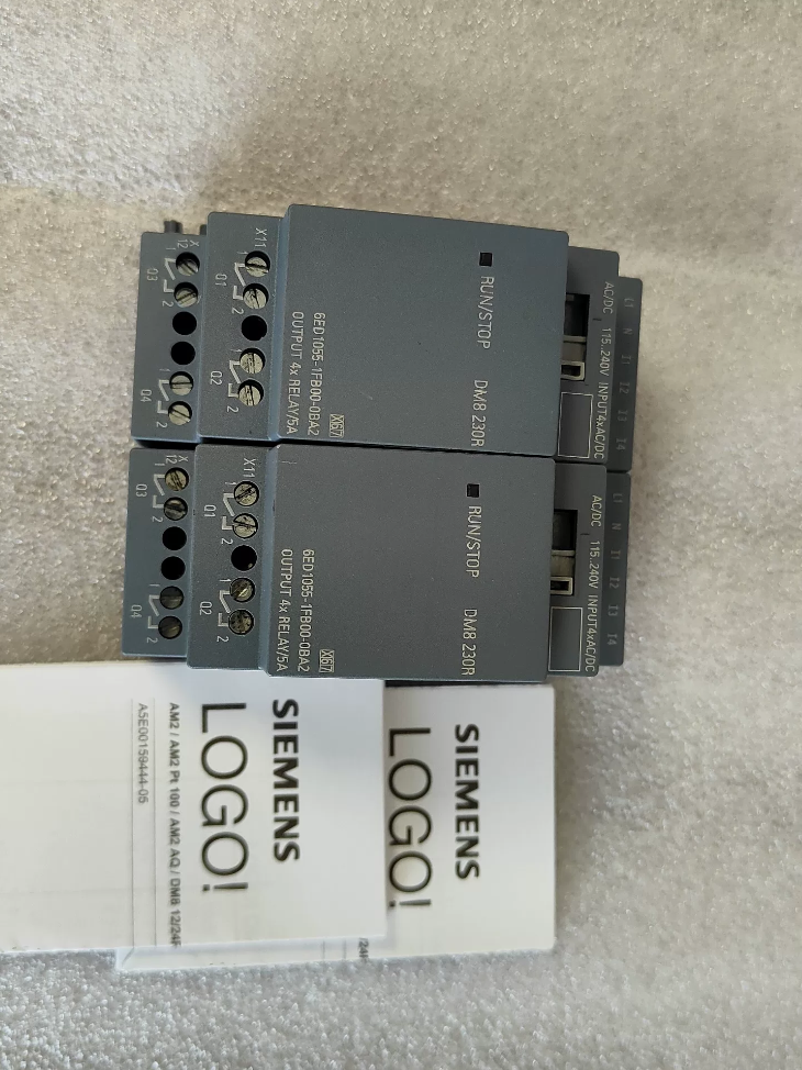

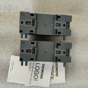
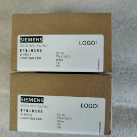
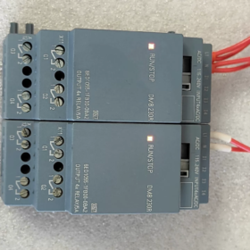
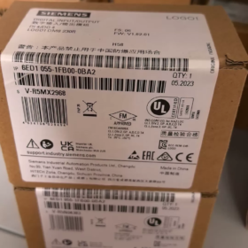
Nome completo: LOGOTIPO! DM8 230R Digital I/O Módulo de Expansão (LOGOTIPO! 8 Série)
- Interpretação de código modelo
6ED1055-1FB00-0BA2
6ED1055: Prefix for LOGO! 8 series expansion modules
1Facebook: DM8 230R, 115/230 Fonte de alimentação V CA/CC, 4DI/4DO relay output
00: Versão de hardware
0BA2: Firmware version (LOGOTIPO!8 plataforma, incompatible with LOGO!6/7 (0BA6/0BA7) main units)
- Especificações elétricas principais
| Item | Especificação |
| Fonte de energia | 115~230 V AC/DC (85~265 V AC; 100~253 V DC) |
| Entrada Digital DI | 4 canais, universal AC/DC signal |
| Lógica 0: <40 V AC /<30 V DC | |
| Lógica 1: >79 V AC />79 V DC | |
| Input delay: 0→1=40 ms; 1→0=75 ms | |
| Saída digital DO | 4 channels relay normally-open isolated contacts |
| Carga resistiva: 5 UM / 250 V e | |
| Carga indutiva: 3 UM / 250 V e | |
| Minimum load current: 100 mA | |
| Frequência máxima de comutação: 2 Hz (resistivo); 0.5 Hz (indutivo) | |
| Montagem | 35 mm trilho DIN, largura 2 O (35.5 milímetros) |
| Dimensões Gerais | W35.5 × H90 × D58 mm |
| Classe de Proteção | IP20 (apenas para instalação em gabinete) |
| Temperatura ambiente operacional | -20 ℃ ~ +55 ℃, sem condensação |
| Peso | Aprox.. 0.17 kg |
- Compatibility Instructions
✅ Supported Main Units: LOGOTIPO! 8 / 8.2 / 8.3 (0BA8 and later firmware)
Typical main unit models: 6ED1052-1FB08-0BA0, 6ED1052-1FB08-0BA1 and other 230 V main units
❌ Not Supported: LOGOTIPO! 6, LOGOTIPO!7 (0BA6/0BA7) main units. Backplane bus protocol differs, communication not available
- Definição de terminal (Principal: Poder & Entrada; Fundo: Saída)
Upper Terminals (Fonte de energia + Entrada)
L1, N: Module operating power supply
I1, I2, I3, I4: 4 entradas digitais
Lower Terminals (Saída de relé)
1º trimestre, 2º trimestre, 3º trimestre, 4º trimestre: 4 independent relay normally-open contact groups (2 terminals per channel, no common terminal)
⚠️ Importante: Four relays are electrically isolated; different voltage circuits can be connected to each channel independently
- Cenários típicos de aplicação
Small HVAC control, bomba de água & controle do ventilador, circuitos de iluminação, door interlock, simple conveyor lines. Ideal for sites equipped with existing 220 V AC sensors and contactor circuits without additional DC power supply.
- Diretrizes de seleção & Armadilhas Comuns
- Input signal must exceed 79 V to be reliably recognized as logic 1; low voltage signals cannot be used.
- Relay mechanical contacts not suitable for high-frequency switching. Select transistor output modules for frequent operation.
- Maximum expansion limit: A single LOGO! main unit can connect up to 4 módulos de expansão.
- All input channels are recommended to use the same phase power. Do not connect I1~I4 across different phases to avoid false triggering caused by induced voltage.
- Install RC snubbers or freewheeling diodes in parallel with inductive loads (contatores, válvulas solenóides) to extend relay service life.
- Comparação com modelos de séries semelhantes
6ED1055-1FB10-0BA2 (DM16 230R): 8DI+8DO relay version with doubled I/O capacity
6ED1055-1HB00-0BA2 (DM8 24R): 24 V DC powered version
Complete Technical Documentation for Siemens 6ED1055-1FB00-0BA2 (LOGOTIPO! DM8 230R)
- Informações básicas do produto
Pedido nº.: 6ED1055-1FB00-0BA2
Nome do produto: LOGOTIPO! DM8 230R Digital Expansion Module (LOGOTIPO!8 Série)
Função: 4DE / 4DO relay output expansion module
Posicionamento: Extend I/O capacity for LOGO!8/8.2/8.3 main units, cannot run standalone
- Full Model Code Interpretation
6ED1055 1FB00 0BA2
- 6ED1055: LOGOTIPO! 8 series expansion module category
- 1Facebook: DM8 230R, 115~230 V AC/DC power supply, 4-channel AC input, 4 independent normally-open relay outputs
- 00: Revisão de hardware
- 0BA2: Firmware version (LOGOTIPO!8 plataforma, incompatible with LOGO!6/7 (0BA6/0BA7) controladores)
- Detailed Electrical Specifications
3.1 Fonte de energia
| Parâmetro | Especificação |
| Tensão nominal | 115…230 V AC/DC |
| Faixa operacional | AC: 85~265 V; CC: 100~253 V |
| Faixa de frequência | 47~63Hz |
| Module Power Consumption | Máx.. 2.2 VA |
3.2 Entrada Digital DI (I1, I2, I3, I4)
Quantidade: 4-channel universal AC/DC input
Lógica 0: <40 V AC / <30 V DC
Lógica 1: >79 V AC / >79 V DC
Input response delay: 0→1: 40 EM; 1→0: 75 EM
Tipo de entrada: Passive AC voltage input, 24 V DC signals are not allowed
Maximum cable length: 100 eu (unshielded cable)
3.3 Relay Output DO (Q1~Q4, isolated normally-open contacts)
⚠️ Four relays are mutually isolated; different voltage circuits can be wired to each channel
|Tipo de carga|Avaliação de contato|
| —| —|
|Carga resistiva (Resistores, Iluminação)|5 UM / 250 V e|
|Carga Indutiva (Contatores, Válvulas Solenóides)|3 UM / 250 V e|
|Minimum Carry Current|100 mA (Poor contact performance may occur below this value)|
|Max Switching Frequency|Carga resistiva: 2 Hz; Carga indutiva: 0.5 Hz; Mechanical no-load limit:10 Hz|
|Prohibited Operation|Parallel connection of multiple output contacts for current boosting is forbidden|
- Mecânico & Parâmetros Ambientais
Montagem: 35 trilho DIN padrão mm
Largura: 2 O (35.5 milímetros)
Dimensões Gerais: W35.5 × H90 × D58 mm
Peso: Aprox.. 170 g
Classe de Proteção: IP20 (gabinete interno apenas para uso)
Temperatura operacional: -20 ℃ ~ +55 ℃ (condensação proibida)
Armazenar & Temperatura de Transporte: -40 ℃ ~ +70 ℃
Umidade relativa: 5% ~ 95%, sem condensação
Resistência à vibração: Em conformidade com IEC 60068-2-6
- Definição de terminal
Upper Terminals (Fonte de energia + Entrada)
L1, N: Module operating power supply 115~230 V AC/DC
I1, I2, I3, I4: 4 entradas digitais
Lower Terminals (Saída de relé)
Q1 two terminals: 1st relay normally-open contact
Q2 two terminals: 2nd relay normally-open contact
Q3 two terminals: 3rd relay normally-open contact
Q4 two terminals: 4th relay normally-open contact
- System Compatibility Rules
✅ Supported Main Units (LOGOTIPO!8 Plataforma)
6ED1052-1FB08-0BA0, 6ED1052-1FB08-0BA1, all LOGO!8.2 / 8.3 230 V controllers
Maximum expansion quantity: Até 4 expansion modules per LOGO! unidade principal
❌ Incompatible Equipment
LOGOTIPO!6 (0BA6), LOGOTIPO!7 (0BA7) legacy controllers. Backplane communication protocol mismatch, cannot be recognized.
- Software Configuration Requirements
Software de programação: LOGOTIPO! Soft Comfort V8.0 or higher
- Select corresponding expansion module model in project hardware catalog;
- I/O addresses of expansion modules automatically follow main unit addresses, no manual assignment required;
- Verify hardware list before program download to avoid errors caused by version mismatch.
- Certificações
CE, UL, CSA, CQC; Em conformidade com EN 61010-1, EM 55011 (EMC Class B, applicable for commercial building environments)
- Diretrizes de implementação de engenharia (Especificações oficiais)
- RC snubbers must be connected in parallel with inductive loads (válvulas solenóides, bobinas do contator) for AC circuits to extend relay lifespan.
- All input channels are recommended to adopt power supply from the same phase. Do not connect input terminals across different phases to prevent false triggering induced by stray voltage.
- Mechanical relay contacts have limited service life. Select transistor output modules (DM8 24T) for high-frequency start-stop applications.
- The module must be installed horizontally; vertical inverted installation is prohibited.
- Maintain heat dissipation clearance in control cabinets to avoid heat accumulation when multiple modules are mounted side by side.
- Comparison Table of Similar Models
| Número do pedido. | Modelo | Fonte de energia | Configuração de E/S | Tipo de saída |
| 6ED1055-1FB00-0BA2 | DM8 230R | 115~230 V AC/DC | 4D/4C | Relé |
| 6ED1055-1FB10-0BA2 | DM16 230R | 115~230 V AC/DC | 8D/8C | Relé |
| 6ED1055-1HB00-0BA2 | DM8 24R | 24 Em DC | 4D/4C | Relé |
Engineering Application Cases for Siemens 6ED1055-1FB00-0BA2 (LOGOTIPO! DM8 230R)
Principais vantagens: Direct acquisition of 115~230 V AC/DC signals; isolated relay contacts directly drive 220 V loads without additional DC power supply. Matched with LOGO! 230RCE main unit (6ED1052-1FB08-0BAx). Suitable for new construction and retrofit projects with fully AC control circuits on site.
Alocação de E/S: 4DE (220 V AC input) + 4 independent normally-open relay outputs
Caso 1: Dual Sewage Pump Automatic Alternation Control for Basement Sump (Building Water Supply & Drenagem)
- Project Requirements
Two 220 V sewage pumps for underground parking sump; high/low level float switches with 220 V contact signals.
High water level: Start pumps; ultra-high level: Dual pumps run simultaneously + audível & alarme visual;
Low water level: All pumps stop;
Automatic timing alternation between main/standby pumps for uniform wear; Manual/Auto switching and fault feedback function.
- Configuração de hardware
Unidade Principal: 6ED1052-1FB08-0BA1 (LOGOTIPO! 230RCE, onboard 8DI/4DO)
Módulo de Expansão: 6ED1055-1FB00-0BA2 ×1 (DM8 230R)
- Atribuição de E/S
Onboard Channels of Main Unit
I1: Auto/Manual Switch; I2: Manual Start Pump 1; I3: Manual Start Pump 2; I4: Parada de Emergência;
1º trimestre: Contactor of Pump 1; 2º trimestre: Contactor of Pump 2;
Expansion Channels of DM8 230R
I5 (Module I1): Low Level Float Switch; I6 (Module I2): High Level Float Switch; I7 (Module I3): Ultra-High Level Float Switch; I8 (Module I4): Poupar;
Q5 (Module Q1): Ultra-high level alarm buzzer; Q6 (Module Q2): Fault indicator light; Q7, Q8: Poupar
- Solution Highlights
Float switches connect directly to module 220 V inputs without intermediate relays. Four isolated relay contacts can drive alarms and indicator lights separately with independent power circuits. No extra DC24V power supply required inside control cabinet, simplificando a fiação.
Caso 2: Fresh Air & Exhaust Fan Interlock Control for Office Building (AVAC)
- Project Requirements
Four 220 V fresh air/exhaust fans with scheduled operation, temperature linkage, fan running feedback and fault alarm. Main unit onboard I/O insufficient, expanded by additional module.
- Hardware List
LOGOTIPO! 230RCE Main Unit + 6ED1055-1FB00-0BA2 ×1
- Module Utilization
Canais DI: 4-channel contactor running feedback signals (220 V);
FAZER Canais: Control contactors for extra two exhaust fans, fault audible & alarme visual, system running indicator light.
- Engineering Features
All control signals are 220 V e; isolated relay contacts allow different phase power feeding. Compact 2TE width saves DIN rail space for wall-mounted small control cabinets.
Caso 3: Timed Group Control of Plant Lighting (Building Lighting System)
- Requisitos
Multiple groups of 220 V lighting circuits for plant road and perimeter lighting; Time-based staged switching via internal real-time clock; Local manual pushbutton override; Fault status feedback.
- Configuração de hardware
LOGOTIPO! 230RCE (Built-in Real-Time Clock) + DM8 230R (6ED1055-1FB00-0BA2)
- Module I/O Assignment
DE: 4-channel local manual pushbuttons (220 V signal);
FAZER: Drive AC contactor coils for 4 lighting groups.
- Motivo de seleção
Module relay supports maximum 5 Uma carga resistiva, capable of directly driving small contactors. Lighting circuits are electrically isolated; single circuit failure will not affect others.
Caso 4: Simple Automatic Transfer Switch for Dual Power Supply of Small Pump Station
- Requisitos de Processo
Two 220 V control power sources (principal + espera). Automatically switch to standby power upon main power failure; interlock to prevent parallel operation; status indication and fault alarm available.
- Configuração de hardware
LOGOTIPO! 230RC Main Unit + 6ED1055-1FB00-0BA2
- Atribuição de E/S
Expansion DI: Dual power supply voltage detection feedback signals;
Expansion DO: Control closing coils of two circuit breakers and switching completion indicator.
This configuration is widely adopted in power distribution renovation projects and listed as official typical application by Siemens.
Caso 5: Greenhouse Evaporative Cooling Fan & Spray Solenoid Valve Interlock Control (Agricultural Automation)
Requisitos
Automatically activate cooling fans and spray solenoid valves when temperature & humidity exceed threshold; delay shutdown; local manual buttons and equipment fault feedback.
Hardware
LOGOTIPO! 230RCE + DM8 230R
Expansion DI: Manual pushbuttons, thermal relay fault feedback of fans;
Expansion DO: 220 V spray solenoid valve, standby fan contactor.
Perceber
Solenoid valves belong to inductive loads. Install AC RC snubbers in parallel with relay outputs to extend relay operating life.
Caso 6: Portão de Segurança, Conveyor and Warning Light Interlock for Light-Duty Conveying Equipment (OEM Machinery)
Lógica de Controle
Conveyor allowed to start only when safety guard gate is closed; conveyor stops immediately once gate opens; warning light stays on and buzzer sounds intermittently during operation; emergency stop has highest priority.
Configuração de hardware
LOGOTIPO! main unit I/O capacity insufficient, expanded via 6ED1055-1FB00-0BA2:
DE: Safety door limit switch, parada de emergência, botão de reinicialização;
FAZER: Conveyor contactor, audível & alarme visual.
General Engineering Mandatory Specifications for All Cases
- ✅ Input Wiring Rule: Todos 4 DI channels must be powered by the same phase L + N. Do not wire I1~I4 across different live phases to avoid false triggering caused by induced voltage.
- ✅ Relay outputs are isolated normally-open contacts; different voltage circuits can be wired to each channel.
- ✅ Snubber components are mandatory for inductive loads (contatores, válvulas solenóides).
- ✅ Maximum 4 expansion modules can be cascaded with one LOGO! unidade principal.
- ✅ Only compatible with LOGO!8 / 8.2 / 8.3 main units (0BA8 firmware). LOGOTIPO!7 and earlier versions are not supported.
- ✅ Cannot operate independently; must be stacked on the right side of LOGO! main unit via expansion bus.





NH42-63-318x560.png "Chaves de transferência automática tipo PC CHINT (ATS)NH42-63/4SZ")



