 Schütz,Leistungsschalter,Sensor,Encoder,SPS,Konverter

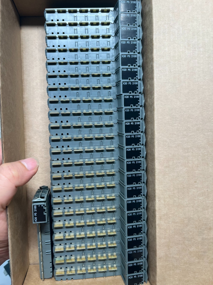

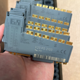
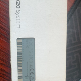
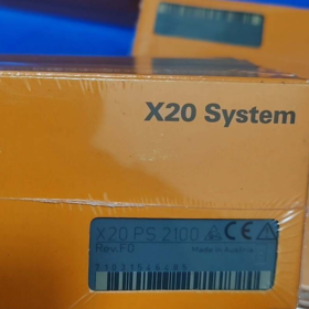
B&R X20PS2100 Installationshandbuch (Engineering Version, compiled per official B&R X20 System Manual)
Modell: X20PS2100; Conformal coated variant: X20cPS2100
Vollständiges Modell: X20PS2100 (Conformal Coated Version: X20cPS2100)
Funktion: Internal I/O power supply module for X20 system
✅ Supplies power only to the internal I/O electronics on the backplane segment
❌ Does NOT provide power for X2X Link bus (Kritische Unterscheidung)
Simple explanation: Powers the electronic circuits of DI/DO/AI/AO modules on the local backplane segment; cannot supply power across segments for X2X bus expansion
- Grundlegende elektrische Spezifikationen
| Artikel | Parameter |
| Eingangsspannung | 24 VDC, Toleranz -15% ~ +20% |
| Max feed-in current | 10 A (external circuit) |
| Module power consumption | Bus side: 0.2 W; I/O circuit: 0.6 W |
| Elektrische Isolierung | No galvanic isolation between I/O feed and backplane |
| Kurzschlussschutz | No built-in fuse. External circuit fuse is mandatory |
| Enclosure protection | IP20 |
| Montageschiene | 35 mm DIN-Schiene, module width 12.5 mm |
Ambient Temperature Ratings
Horizontale Montage: -25 ℃ … +60 ℃
Vertikale Montage: -25 ℃ … +50 ℃
Elevation above 2000 M: Derate maximum ambient temperature by 0.5 ℃ per 100 M
- Obligatorisches passendes Zubehör (Ordered Separately)
- Bus Module (Select one)
X20BM01: Power supply bus module, without node address switch
X20BM05: Power supply bus module, with X2X node address switch
Funktion: Blocks power transmission to the left backplane for segmented power feeding
- Klemmenblock: X20TB12 (12-Stift, 24 VDC keyed terminal)
- Comparison with Peer Power Supply Modules (Key for Selection)
| Modell | Power Supply Target | Supports X2X Link Bus Power | Typische Anwendung |
| X20PS2100 | Internal I/O only | ❌ Nicht unterstützt | Segmented power supply for local I/O on standalone machines, short backplanes |
| X20PS3300 | Internal I/O + X2X Link Bus | ✅ Supports cross-segment expansion | Distributed remote stations, multi-segment X2X Link networks |
⚠️ Common mistake: Attempting to drive X2X expansion modules using X20PS2100 → System will not operate. X20PS3300 must be used.
- LED Indicator Definition
LAUFEN (Grün): Steady ON = Module normal; OFF = No 24V supply / Fehler
ERR (Rot): AN / Flashing = Abnormal supply, Überlast, wiring fault
- Verdrahtung & Engineering Guidelines
- Terminals accept +24V / 0V feed to power the current backplane segment;
- X20BM01/X20BM05 blocks power to the left, enabling independent segmented power feeding for multiple modules to mitigate voltage drop;
- Recommended external protection: Max. 10 A slow-blow fuse;
- Hot swapping is not supported;
- Multiple X20PS2100 modules can be connected in parallel on one backplane segment to increase available supply current.
- Zertifizierungen
CE, UL cULus, ATEX Zone2, Class I Div.2 (suitable for hazardous area Zone2), DNV, ABS Marine Approval, KC
- Typische Anwendungsszenarien
Local I/O stations for machine tools, Verpackungslinien, Spritzgießmaschinen; segmented power supply for X20 local stations on small-to-medium equipment without X2X cross-segment expansion.
- Schnelle Fehlerbehebung
- RUN-LED AUS: Missing external 24 VDC, loose X20TB12 terminals, reversed power polarity
- ERR LED steady ON: Backplane short circuit, overcurrent beyond limit
- Partial modules fail to power up: Check orientation of X20BM01/X20BM05, verify segmented power logic
Falls erforderlich, Ich kann dafür sorgen:
Complete pin assignment of X20TB12
Text schematic of standard segmented backplane wiring
Extracted key pages from official X20PS2100 datasheet
Or evaluate whether upgrading to X20PS3300 is required for your application.
Funktionsdefinition: X20 system internal I/O power supply module (supplies power only to local backplane I/O circuits, X2X Link bus power is not supported)
⚠️ Important Note: B&R does NOT issue an independent standalone installation manual for X20PS2100. Relevant specifications are documented in X20 System User’s Manual. This document is standardized for on-site commissioning and cabinet design.
Inhaltsverzeichnis
- Pre-installation Safety Instructions
- List of Mandatory Matching Components
- Mechanische Installationsspezifikationen
- Backplane Layout Rules (Critical – Frequent Source of Errors)
- X20TB12 Terminal Pinout & Verkabelungsspezifikationen
- LED Status Diagnosis
- Elektrische Spezifikationen & Umgebungsbedingungen
- Fuse Selection & Earthing Guidelines
- Standard Power-on Commissioning Procedures
- Fault Diagnosis Matrix
- Auswahl & Installation Taboos
- Pre-installation Safety Instructions
- All installation and disassembly operations must be performed with 24 VDC power disconnected. Hot swapping is NOT supported.
- Modules are rated IP20 and shall only be installed inside electrical control cabinets.
- Implement ESD protection (wear anti-static wrist strap) before handling to prevent electrostatic damage to backplane circuits.
- Strictly prohibit reverse polarity input; avoid input voltage exceeding 28.8 VDC.
- No galvanic isolation exists between I/O supply and backplane. Not applicable for signal circuits requiring electrical isolation.
- Temperature derating is mandatory for installation elevation above 2000 M.
- Mandatory Matching Components (Supplied Separately, not included with module)
| Teilenummer | Beschreibung | Anwendungshinweise |
| X20BM01 | Power Supply Bus Module | Blocks I/O power to left; no node switch, preferred for local I/O |
| X20BM05 | Power Supply Bus Module | Blocks I/O power to left; with X2X node address switch, used for remote stations |
| X20TB12 | 12-Stift 24 VDC keyed terminal block | Mandatory fitting; X20TB06 cannot be substituted |
Optional spares: X20 label strips, wire end ferrules for push-in terminals
- Mechanische Installationsspezifikationen
3.1 DIN Rail Requirement
Standard 35 mm TH35 DIN rail; module width: 12.5 mm
3.2 Montageausrichtung & Temperature Limits
| Montageart | Betriebstemperatur | Bemerkungen |
| Horizontale Montage (Empfohlen) | -25 ℃ … +60 ℃ | Module label readable forward |
| Vertikale Montage | -25 ℃ … +50 ℃ | Reserve upper and lower clearance for heat dissipation |
Lagerung / Transporttemperatur: -40 ℃ ~ +85 ℃
Relative Luftfeuchtigkeit: 5%~95%, Kondensation ist verboten
Elevation 2000 M: Reduce maximum ambient temperature by 0.5 ℃ per 100 M
3.3 Installationsschritte
- Hook the top latch onto DIN rail;
- Press down the bottom of the module until an audible click confirms secure locking;
- Butt tightly against adjacent modules to complete backplane interconnection;
- Entfernung: Lift the bottom latch upward and pull outward to extract the module.
- Backplane Layout Rules (Core Engineering Requirement)
✅ Standard Layout Order (Left to Right)
`X20BM01 / X20BM05 → X20PS2100 → DI/DO/AI/AO I/O Modules`
Grundprinzip
Hardware characteristic of X20BM01/X20BM05: Blocks I/O power transmission to the left
→ X20PS2100 supplies power only to all modules on its right side; modules on the left receive no power from this unit.
Permitted Configurations
- Single backplane segment: BM01 + PS2100 + I/O-Module
- Multi-segment independent power feeding: `BM01+PS2100 + E/A + BM01+PS2100 + I/O` for voltage drop reduction
- Multiple X20PS2100 modules can be paralleled on the same segment to increase total supply capacity.
❌ Strictly Forbidden Layout Errors
- Place PS2100 on the left side of the bus module
- Use PS2100 to power X2X Link expansion backplanes (cross-segment power supply fails; X20PS3300 required)
- Omit X20BM01/X20BM05 directly in front of PS2100, causing reverse power crosstalk between backplane segments
- X20TB12 Pin Assignment for X20PS2100
Active pins among terminals 1~12:
| Terminal-Nr. | Signal Definition | Beschreibung |
| 1 | +24V I/O | Extern 24 VDC positive input |
| 2 | +24V I/O | Parallel positive terminal (supports dual incoming cables) |
| 11 | GND (0V) | External DC negative |
| 12 | GND (0V) | Parallel negative terminal |
Verkabelungsspezifikationen
- Kabelquerschnitt: 0.5 ~ 2.5 mm² stranded copper wires; wire end ferrules recommended for push-in terminals
- Route power cables separately from analog signal cables to minimize interference
- Do NOT connect field sensor loads directly to these terminals. Terminals are solely for backplane power feed.
- Definition der LEDs auf der Vorderseite
Two LEDs on module front: LAUFEN (Grün), ERR (Rot)
| LAUFEN | ERR | Status Description | Korrekturmaßnahme |
| Ständig AN | AUS | Normaler Betrieb | Keine Aktion erforderlich |
| AUS | Any state | No 24V supply, lose Anschlüsse, umgekehrte Polarität | Ausschalten, retighten wiring and verify polarity |
| Ständig AN | Ständig AN | Backplane short circuit / Severe overload | Power off and locate short-circuit point by removing I/O modules sequentially |
| Ständig AN | Intermittent flashing | Unterspannung (unten 20.4 VDC) | Messen 24 V supply output and cable voltage drop |
- Elektrische Spezifikationen
Nominal Input: 24 VDC; Betriebsbereich: 20.4 VDC ~ 28.8 VDC (-15% ~ +20%)
Maximum feed-in current: 10 A
Module self-consumption: Bus side 0.2 W; I/O circuit 0.6 W
Isolierung: No galvanic isolation between I/O supply and backplane
Schutzklasse: IP20
- Sicherung & Earthing Engineering Specifications
- Mandatory external fuse requirement
Install a ≤10 A slow-blow (time-delay) fuse upstream of the circuit
❌ No internal fuse fitted in the module; short-circuit risk may permanently damage the backplane!
- Earthing Recommendations
Implement single-point earthing for 24 VDC 0V; separate cabinet protective earth (PE) and power ground wiring.
For high-interference environments, fit EMC filter capacitor between 0V and PE.
- Standard Power-on Commissioning Procedure
- Complete mechanical installation and confirm full backplane interconnection;
- Wire X20TB12 power terminals and double-check polarity;
- Verifizieren 24 VDC supply via multimeter;
- Close external power switch;
- Confirm RUN LED steady ON and ERR LED extinguished;
- Scan hardware via Automation Studio to verify all I/O modules on this segment are detected normally;
- Measure backplane supply voltage at remote modules to confirm acceptable voltage drop.
- Fault Diagnosis Matrix
| Fehlersymptom | Grundursache | Lösung |
| RUN LED does not light | NEIN 24 V-Versorgung, lose Anschlüsse, umgekehrte Polarität | Ausschalten, retighten terminals and confirm polarity |
| ERR LED steady ON, module inoperable | Backplane short circuit, faulty I/O module | Remove I/O modules one by one to identify faulty unit |
| Partial I/O modules fail to power up | Incorrect orientation of BM01 module, wrong segmented power layout | Adjust layout; ensure bus module sits left of PS2100 |
| Low voltage at remote backplane modules | Übermäßige Belastung, overly long cables | Add extra PS2100 for segmented feeding; upgrade to larger cable cross-section |
| Complete failure of X2X remote I/O stations | X20PS2100 incorrectly deployed; cannot supply X2X bus power | Replace module with X20PS3300 |
- Auswahl & Installation Taboos Summary
- X20PS2100 cannot supply power for X2X expansion links. Select X20PS3300 for distributed remote stations.
- X20BM01/X20BM05 cannot be omitted.
- Hot swap is prohibited.
- Cannot be used as power output for external sensors and actuators; only for internal X20 backplane electronics.
- For safety circuits requiring I/O supply disconnection, hardware revision Rev.F0 or newer is mandatory.
Access to Official Original Manual
Download X20 System User Manual (Document No.: UM200.440) from B&R official website; section 4.27 contains full specifications of X20PS2100.
Auf Anfrage kann ich zur Verfügung stellen:
- Terminal definitions ready for direct import into EPLAN
- Text-based backplane wiring schematic
- Full comparison table between X20PS2100 and X20PS3300 for selection
Häufige Fehler, Grundursachen & Standard Remedial Measures for B&R X20 I/O System
Covers backplane, power modules (X20PS2100/PS3300), bus modules, digital/analog I/O modules, X2X Link expansion and Automation Studio recognition issues. Classified into four categories: Hardware faults, wiring faults, configuration faults, EMC interference.
Applicable hardware: X20CPU, X20BC bus controller, X20PS power modules, X20DI/DO/AI/AO, X20BM bus modules, X2X remote stations
- Power Supply Related Faults (Am häufigsten, Especially with X20PS2100)
1.1 Partial I/O modules fail to power up, undetected in Automation Studio
Symptom: Front modules on one backplane segment operate normally, remote modules fail to start; RUN-LED AUS
Typical Causes
- X20BM01/X20BM05 installed backwards or misplaced, blocking power transmission
- X20PS2100 only supports local segment I/O power; cannot feed X2X remote stations
- Heavy backplane load, thin cables leading to undervoltage below 20.4 VDC at remote positions
- Blown external fuse, loose TB terminals
Abhilfemaßnahmen
Layout rule: Bus module installed left of power module, power propagates rightward
X20PS3300 is mandatory for remote X2X stations
Deploy multiple PS2100 for segmented feeding on long backplanes
1.2 ERR Red LED steady ON on X20PSxx modules
Symptom: RUN Green LED ON, ERR steady ON / flashing
Ursachen
- Backplane internal short circuit (damaged I/O module, deformed backplane pins)
- Transient overload, supply voltage out of tolerance
- Failed I/O module pulling down backplane supply
Diagnose: Power off and remove I/O modules sequentially from right to left to locate faulty hardware.
1.3 RUN LED completely OFF on power supply module
Missing external 24 VDC, reversed polarity on X20TB12 terminals, incompletely latched terminals.
- Rückwandplatine & Mechanical Contact Faults
2.4 Intermittent module dropout
Symptom: Modules randomly reported missing in Automation Studio; fault appears after cabinet vibration or door operation
Grundursachen
- Incomplete backplane interconnection between adjacent X20 modules
- Loose DIN rail; vibration causes intermittent contact
- Oxidation / deformation of backplane spring contacts due to repeated disassembly
Countermeasure: Re-seat all modules; minimize frequent disassembly under high-vibration operating conditions.
2.5 Single module undetected while other modules on same backplane work normally
- Damaged backplane connector on the module
- Hardware revision mismatch with project configuration
- Permanent internal hardware failure of module
- X2X Link Remote Expansion Bus Faults (Common on-site issue)
3.6 Complete loss of communication to all modules on remote X2X station
Symptom: Fault reported for entire remote station; X2X bus error displayed on master controller
Primary triggers:
- X20PS2100 incorrectly used at remote station (unable to supply X2X bus power)
- Damaged X2X communication cable; missing or duplicate 120 Ω terminating resistor
- Duplicate or incorrectly set node address switches on X20BM05
- Fehlen 24 V supply to remote station
✅ Standard rule: Install only one 120 Ω terminating resistor at one end of X2X bus
3.7 Frequent X2X communication errors, cyclic station dropout
Almost always induced by EMC interference:
X2X cables routed parallel to high-power drive cables over long distances
Multiple earthing points for control cabinets, potential difference between 0V and PE
Missing filters for inverters and servo drives
- Digitale I/O (AUS / TUN) Typische Fehler
4.8 DI input inactive despite valid signal measured externally
- Insufficient backplane supply voltage
- Fehlen / broken COM common wiring for DI channels
- Sensor sourcing/sinking type mismatched with DI module specifications
- Gebrannter Eingangskanal
4.9 DO output fails to drive load / permanently ON / AUS
- Missing external load power supply for DO modules (Backplane supply ≠ actuator supply on most X20DO modules)
- Blown on-board electronic fuse due to channel short circuit
- Excessively long task cycle causing delayed output refresh
- No freewheeling diode fitted for inductive loads (Magnetventile), leading to channel breakdown
4.10 Massive damage to multiple DO channels
High probability: Surge voltage breakdown caused by inductive loads without freewheeling protection.
- Analoge E/A (KI / ZUM) Frequent Faults
5.11 AI signal drift, unstable fluctuating readings
1 Grundursache: Elektromagnetische Störungen
- Unshielded analog cables; shield grounded at both ends (shield must be single-end grounded inside cabinet)
- Analog cables routed within same cable duct as power cables
Other causes:
Excessive voltage drop at sensor supply
Open circuit in 4~20 mA loop (module usually displays minimum value)
Poor contact at voltage input terminals
5.12 AI value locked at upper or lower limit
Open circuit in 4~20mA loop → reading near minimum (~4mA);
Short circuit at sensor → reading near maximum (~20mA).
5.13 AO output fails to reach setpoint, insufficient drive capability
Load impedance exceeds module specification; loose wiring terminals; insufficient backplane supply.
- Software & Automation Studio Configuration Faults (Easily misjudged as hardware failure)
6.14 Persistent “Module mismatch” error after project download
Symptom: Hardware physically installed, but AS reports module mismatch
Ursachen:
- Wrong model selected in project hardware tree
- Module hardware revision too old, incompatible with active firmware
- Hardware scan not updated after module replacement
6.15 Module detected normally, but I/O signals do not refresh
- Falsche E/A-Zuordnungsadresse
- I/O processing not enabled within assigned task
- Channel enable parameter disabled in module configuration (supported on selected modules)
6.16 Random faults induced by firmware incompatibility
CPU firmware revision outdated and incompatible with newer X20 modules; symptoms include random module dropout and communication instability.
- Complex EMC & Earthing Related Faults (Hardest to troubleshoot)
Typical feature: Fault occurs randomly; system works under no-load condition, errors emerge once loads are activated
- Multiple earthing points on 24 V 0V and PE create ground loops → analog signal drift, intermittent X2X dropout
- Unshielded power cables for inverters and servos induce interference onto backplane bus
- Isolation missing between 24 V supplies of different control cabinets, generating potential difference and communication disturbance
Empfohlene Spezifikation: Single-point earthing for 24 VDC 0V; cable shield grounded only inside the control cabinet.
- Environmentally Induced Faults
- Condensation → backplane leakage, random short circuits, permanent module burnout
- Operating temperature exceeded (Horizontal 60 ℃, Vertikal 50 ℃) → abnormal module behavior, spontaneous reset
- Dust and oil contamination on terminals and backplane → poor contact
Standard Tiered Troubleshooting Procedure for On-site Maintenance
- Verify all X20PS power supply units; confirm 24 VDC within range: 20.4~28.8 V
- Define fault scope: Single module fault / Entire backplane segment / All remote X2X stations
- Entire segment fault → Inspect power modules, BM layout, X2X bus power (Distinguish PS2100 and PS3300)
- Single channel fault → Inspect external wiring, sensors/actuators, gemeinsame Terminals, load surge protection
- Random intermittent faults → Prioritize inspection of mechanical seating, EMC interference and earthing system





NH42-63-318x560.png "Automatische Transferschalter vom Typ CHINT PC (ATS)NH42-63/4SZ")



