 Schütz,Leistungsschalter,Sensor,Encoder,SPS,Konverter

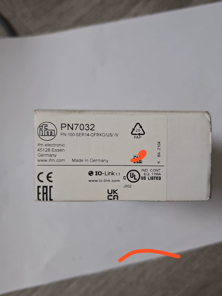

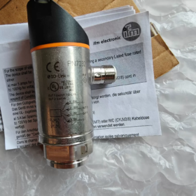
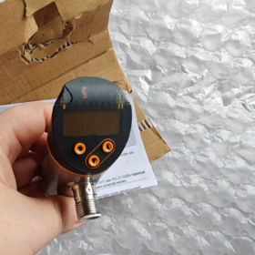
Vollständige Modellnr.: PN-100-SER14-QFRKG/US/ /V
PN7032 belongs to PN70xx series, a relative Drucksensor with digital display, two switching outputs and IO-Link on one channel. It adopts ceramic-capacitive measuring cell, widely used for pressure switches and transmitters in industrial hydraulic and pneumatic systems.
✅ Key Specifications
| Artikel | Parameter |
| Messbereich | 0…10 MPa (0~100 bar), relative pressure |
| Prozessanbindung | G1/4 Innengewinde; rotatable display head |
| Measuring element | Ceramic-capacitive |
| Overpressure | 30 MPa; Berstdruck 65 MPa |
| Ausgabe | 2 x PNP switching outputs; OUT2 multiplexed for IO-Link |
| Stromversorgung | 18…30 V DC; Verpolungsschutz & Kurzschlussschutz |
| Mittlere Temperatur | -25 ~ +80 ℃ |
| Schutz vor Eindringen | IP67; M12 A-coded 5-pin gold-plated connector |
| Anzeige | 4-digit red/green digital display, tri-color status indicator, 3-key menu |
| Switch setting | SP: 0.1~10 MPa; rP reset point; minimum hysteresis 0.05 MPa |
| Antworthäufigkeit | Max. 170 Hz |
| Medium | Primarily for liquids; gas applications above 25 bar require separate evaluation |
✅ Model Code Explanation
PN-100-SER14-QFRKG/US/ /V
PN: Series with display
100: Measuring range 0~10 MPa
S: 2 switching outputs
E: IO-Link function
R: G1/4 Innengewinde
14: M12 5-pin electrical connector
QFRKG: Code for housing, sealing and electrical configuration
✅ Product Features
- IO-Link-Kommunikation: Read real-time pressure, temperature and diagnostic data; remote parameter read/write via PLC, device identification and fault diagnosis supported.
- Rotatable display head for convenient viewing after installation.
- Red/green color-changing display: green within valid pressure range, red when threshold exceeded.
- Ceramic cell, good resistance to pressure spikes and excellent long-term stability.
- Two independent switch points for high/low pressure dual alarm.
- Built-in short-circuit and reverse polarity protection, geeignet für raue Industrieumgebungen.
✅ Typical Applications
Hydraulic station pressure monitoring, lube oil circuits, cooling water systems, high-pressure pneumatic loops, Spritzgießmaschinen, Werkzeugmaschinen, Pumpstationen, Luftkompressoren.
✅ Reference Replacement Models
PN7032 (0~10MPa, G1/4 Innengewinde, IO-Link)
PN7033: 0~2.5MPa
PN7034: 0~1MPa
PN7036: 0~0.25MPa
Notiz: PN7032 is partially phased out. Für neue Projekte, consult IFM PN72 series alternatives. Faden, measuring range, IO-Link and output logic need to be verified.
✅ Pin Assignment (M12 5-pin A-coded)
1: Power +18~30V DC
2: OUT1 (PNP switch)
3: Strom-GND
4: OUT2 / IO-Link
5: Nicht verwendet
✅ Common Troubleshooting
- Keine Anzeige: Check supply voltage and confirm no reverse connection.
- Pressure reading drift: Verify medium temperature and pressure spikes upstream; ceramic cell is vulnerable to continuous overpressure.
- IO-Link communication failure: Check pin 4, IO-Link master baud rate and matched IODD file.
- Switch output not actuating: Enter menu to verify SP/rP setting and output mode (window / Hysterese).
Vergleichstabelle: IFM PN7032 vs PN72 Series (PN7292, Direkter Ersatz)
PN7032: PN-100-SER14-QFRKG/US/ /V (eingestellt)
PN7292: PN-100-REN14-QFRKG/US/ /V (official recommended replacement, 0~10MPa, G1/4 Innengewinde, 2×PNP + IO-Link)
| Vergleichsartikel | PN7032 | PN7292 (PN72 Series Replacement) | Bemerkungen |
| Vollständiges Modell | PN-100-SER14-QFRKG/US/ /V | PN-100-REN14-QFRKG/US/ /V | Identical measuring range: 0…10 MPa (0~100 bar) relative pressure |
| Measuring Cell | Ceramic-capacitive | Ceramic-capacitive | Dasselbe, resistant to pressure spikes, suitable for hydraulic/lube oil |
| Prozessanbindung | G1/4 Innengewinde | G1/4 Innengewinde | Mechanically fully compatible, direct swap-in |
| Electrical Connector | M12 A-coded 5-pin | M12 A-coded 5-pin | Pinout identical, no cable rework required |
| Ausgabekonfiguration | 2×PNP switching outputs, OUT2 multiplexed IO-Link | 2×PNP switching outputs, OUT2 multiplexed IO-Link; output software-selectable PNP/NPN | PN72 adds PNP/NPN software switching |
| Stromversorgung | 18…30 V DC | 18…30 V DC | Gleicher Bereich, reverse polarity & Kurzschlussschutz |
| Overpressure | 30 MPa | 30 MPa | Identisch |
| Burst Pressure | 65 MPa | 65 MPa | Identisch |
| Mittlere Temperatur | −25 ~ +80 ℃ | −25 ~ +80 ℃ | Same temperature range |
| Schutz vor Eindringen | IP67 | IP67 | Same housing protection |
| Anzeige | 4-digit red/green digital display, tri-color status, 3 Schlüssel | 4-digit red/green LED, side status indicators, 3 Schlüssel | Same display logic; display head 360° rotatable |
| IO-Link Version | IO-Link 1.1 | IO-Link 1.1 | IODD files differ; PLC project needs IODD update |
| Switch Point Setup | SP, rP hysteresis; min hysteresis 0.05 MPa | SP, rP hysteresis; min hysteresis 0.05 MPa | Menu logic mostly consistent; PN72 supports more pressure units |
| Antworthäufigkeit | Max. 170 Hz | Max. 170 Hz | Same dynamic response |
| Gesamtdimension | Identical body outline | Identical body outline | No modification to mounting space or bracket |
| Hauptunterschiede | Fester PNP-Ausgang | Software PNP/NPN toggle; more menu parameters; extended diagnostic information; improved service life (>100 million pressure cycles) | ✅ Direct replacement for most applications; ⚠️ IO-Link projects require IODD update |
PN72 Series Selection List for PN70xx Equivalents
| Messbereich | Original PN70xx Model | PN72 Series Replacement | Faden |
| 0~10 MPa /100 Bar | PN7032 | PN7292 | G1/4 Innengewinde |
| 0~2.5 MPa /25 Bar | PN7033 | PN7293 | G1/4 Innengewinde |
| 0~1 MPa /10 Bar | PN7034 | PN7294 | G1/4 Innengewinde |
| 0~0.25 MPa /2.5 Bar | PN7036 | PN7296 | G1/4 Innengewinde |
⚠️ Replacement Engineering Notes
- Mechanische Installation: Thread and physical dimensions are identical; can be directly screwed into existing piping.
- Elektrische Verkabelung: M12 5-pin pinout fully identical, no cable modification needed.
- Switch-only Application (No IO-Link): Direkter Ersatz, re-set SP/rP parameters only; PLC program unchanged.
- IO-Link Application: IODD file update mandatory. PN7032 and PN7292 IODD are not interchangeable; different device ID, PLC will recognize it as new equipment.
- Ausgabetyp: PN7032 fixed PNP; PN7292 factory default PNP, can be switched to NPN via menu.
- Pressure Units: PN72 supports more units (bar/MPa/psi etc.), older PN7032 has fewer unit options.
- Media Note: Ceramic cell, avoid strongly corrosive media; high-pressure gas applications require separate evaluation.
Limitation Statement
PN72 series (PN7292) is functionally compatible replacement instead of 100% firmware identical. Diagnostic parameters and device ID read via IO-Link differ. For pure switch signals, zero-modification replacement; IO-Link projects require PLC IODD update and parameter download.
Complete Installation Instructions for IFM PN7032 Pressure Sensor
PN7032: G1/4 Innengewinde, M12 A-coded 5-pin, ceramic cell, gauge pressure 0~10MPa; Depressurize system and cut off power before installation
- Vorbereitung vor der Installation
- Safety Check
Shut down and depressurize piping; confirm medium, temperature and maximum pressure do not exceed PN7032 specification (medium -25~80℃, overpressure 30MPa).
- Pressure Tap Selection
Liquid medium: Tap taken from side of pipe to prevent air bubbles accumulating on measuring cell.
Gas medium: Tap taken from top of pipe to avoid liquid pooling on cell.
Avoid locations after pumps, valves and elbows with pressure spikes and high turbulence. Add snubber/damper under heavy vibration to protect ceramic cell.
- Piping Pre-treatment
Purge piping to remove metal chips and weld slag; debris can scratch ceramic diaphragm and cause zero drift.
- Sealing Parts Preparation
G1/4 is parallel pipe thread. Do NOT wrap large amount of PTFE tape. Copper gasket or O-ring is preferred. A small amount of thread sealant is allowed, but sealant must not squeeze into pressure chamber, which will permanently damage the cell.
- Werkzeuge: Drehmomentschlüssel, M12 pre-assembled cable, spanner.
- Mechanische Montage (Pressure Piping Connection)
- Align sensor G1/4 thread with pipe fitting, hand-tighten first. Do NOT use spanner on plastic display housing directly.
- Empfohlenes Anzugsdrehmoment: 25~35 N·m. Must use torque wrench. Excessive torque causes housing deformation and ceramic cell cracking; insufficient torque causes leakage.
- Display Head Rotation: After tightening thread, the electronic display head can be rotated 345° for optimal viewing angle. Do not rotate beyond mechanical end stop, forced rotation damages internal wiring.
⚠️ Hinweis: Rotate the upper display head, NOT the pressure thread base.
- Nach der Installation, pressurize slowly and check thread for leakage.
- Elektrische Verkabelung (M12 A-coded 5-pin)
Perform wiring with power OFF. IFM original M12 prefabricated cable recommended. Anzugsdrehmoment des M12-Steckers: 0.6~1.2 Nm to maintain IP67.
| Pin-Nr. | Drahtfarbe | Definition | Bemerkungen |
| 1 | BN Brown | DC+ 18~30V | Macht positiv |
| 2 | WH White | OUT1 (PNP-Schaltausgang) | Switch channel 1 |
| 3 | BU Blue | Gleichstrom- GND | Macht negativ |
| 4 | BK Black | OUT2 / IO-Link | Kanal 2, IO-Link multiplex port |
| 5 | — | Nicht verwendet | Spare pin |
Ausgabe: 2×PNP, max load current 250mA per channel.
IO-Link usage: Stift 4 for IO-Link communication.
Kabelempfehlung: 0.34~0.5mm². Route IO-Link wiring away from frequency converters and high-power power cables to reduce interference.
- Einschalten & Inbetriebnahme
- Double-check wiring for correctness and short circuit; fasten M12 connector.
- Apply DC24V power slowly, display lights up.
- Menu configuration: Set switch point SP, reset point rP, select window / hysteresis mode and pressure unit.
- Zero point verification: Confirm reading near 0 bar when piping is depressurized.
- Pressurize gradually, verify pressure reading and switch output actuation.
- IO-Link application: Import IODD file in PLC, identify device, read pressure, temperature and diagnostic parameters.
- Kritische Installationsverbote (Engineering Key Points)
- ❌ Do NOT mount or demount sensor under pressure; high-pressure ejection may injure personnel and damage equipment.
- ❌ Do NOT use spanner on plastic display housing to tighten thread; only clamp lower metal thread base.
- ❌ Heavy PTFE tape on G1/4 thread; debris entering pressure chamber scratches ceramic cell.
- ❌ Over-tightening torque, may fracture ceramic measuring element.
- ❌ Direct medium impact above 80℃; add cooling buffer for high-temperature media.
- ❌ Operation under heavy shock and continuous vibration without snubber, leading to zero drift and shortened service life.
- ❌ Hot plug/unplug M12 connector, risk of burning output circuit.
- Post-installation Check List
No leakage at thread connection
M12 connector tightened, IP67 intact
Versorgungsspannung: 18~30V DC
No short circuit or reverse polarity
Zero reading normal with no applied pressure
Switch point action normal / IO-Link communication stable
- Replacement Hint for PN7292
Mechanical mounting, Faden, torque and M12 pinout are fully identical; piping and cables remain unchanged. Only IO-Link projects require IODD file update.
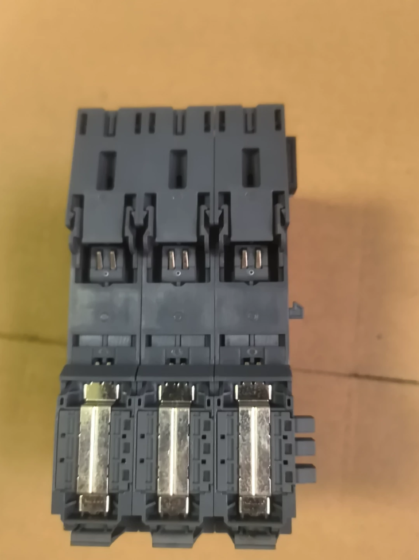



NH42-63-318x560.png "Automatische Transferschalter vom Typ CHINT PC (ATS)NH42-63/4SZ")



