 Schütz,Leistungsschalter,Solarwechselrichter,Stromzähler,Solarbatterien


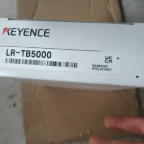
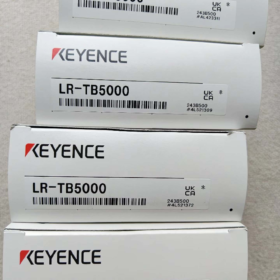
Der KEYENCE LR-TB5000 ist ein TOF-Entfernungslaser mit integriertem Verstärker Sensor der KEYENCE LR-T-Serie. Es handelt sich um ein diffus-reflektierendes Modell für die Fernerkennung, Ausgestattet mit einem geraden Standardkabel und klassifiziert als Laserklasse 2. Übernahme des Time-of-Flight-Messprinzips, Es liefert eine stabile Entfernungsmessung und Erkennung der Anwesenheit von Objekten im Bereich von 60 mm bis 5000 mm. Seine Leistung wird durch die Farbe kaum beeinflusst, Material oder Oberflächenwinkel der Ziele. Mit hoher Schutzart IP65/IP67, Es wird häufig in komplexen Arbeitsbedingungen eingesetzt, beispielsweise in Produktionslinien für die industrielle Automatisierung, Logistik & Lager- und Baumaschinen. Es ist eine gängige Wahl für die Erkennung über große Entfernungen und mit hoher Zuverlässigkeit an Industriestandorten.
- Aufschlüsselung des Modellcodes
Modell: LR-TB5000
| Codesegment | Beschreibung |
| LR-T | Produktserie: Allgemeine Serie von TOF-Lasersensoren mit integriertem Verstärker |
| B | Erkennungstyp: Diffus-reflektierender Typ (kein Reflektor erforderlich, Erkennt Zieloberflächen direkt) |
| 5000 | Maximaler Standarderkennungsabstand: 5000mm (5M), Getestet mit weißem, mattem Papier als Referenz |
| Kein Suffix | Kabelausgang: Gerader Kabeltyp; Laserklasse: Klasse 2 (Konform mit IEC60825-1 und FDA(CDRH) Standards) |
Ergänzende Regeln für Suffixe derselben Serie: Das Suffix „C“ steht für den M12-Steckertyp; Das Suffix „CL“ steht für M12-Stecker mit Low-Power-Laserklasse 1.
- Grundlegende technische Spezifikationen
2.1 Erkennungsleistung
| Parameter | Spezifikation | Bemerkungen |
| Standard-Erfassungsbereich | 60 ~ 5000 mm | Anzeigebereich: 50~5200mm; Getestet auf weißem, mattem Papier |
| Lichtquelle | Roter Halbleiterlaser, Wellenlänge: 660nm | Laserklasse 2, Max. Ausgangsleistung ≤1mW |
| Spotdurchmesser | Variable, ≤φ40mm | Die Spotgröße variiert linear mit dem Erkennungsabstand |
| Ansprechzeit | 5 wählbare Stufen: 1MS / 10MS / 25MS / 100MS / 1000MS | Passen Sie Reaktionsgeschwindigkeit und Erkennungsgenauigkeit nach Bedarf an |
| Ablehnung gegenseitiger Beeinflussung | Bis zu 4 Einheiten desselben Modells können eng in einer Gruppe installiert werden | Die Funktion wird wirksam, nachdem die Interferenzverhinderung aktiviert wurde |
| Erkennungslogik | Mehrere Modi: Schwellenurteil, Fenstervergleich, Spitzenhalt, Tal halten, usw. | Sichtbare Konfiguration über integrierte Tasten |
| Timer-Funktion | AUS / Einschaltverzögerung / Ausschaltverzögerung / One-Shot-Puls (optional) | Die Verzögerungszeit kann über Parameter angepasst werden |
2.2 Elektrische Eigenschaften
| Parameter | Spezifikation |
| Versorgungsspannung | 12~24 VDC (Welligkeit von Spitze zu Spitze ≤10 %) |
| Aktueller Verbrauch | ≤45mA (24VDC-Versorgung, keine Ladung) |
| Ausgang schalten | Umschaltbarer offener NPN/PNP-Kollektor; Nennspannung unter 30 VDC, 50mA; NO/NC wählbar |
| Analoger Ausgang | Wählbarer 4-20-mA-Strom / 0~10V Spannung; Geteilter Pin mit externem Eingang |
| Externer Eingang | Unterstützt Fernabstimmung und Modusumschaltung; Gemeinsamer Pin mit Analogausgang |
| Kommunikationsprotokoll | IO-Link v1.1 wird für die Remote-Parameterkonfiguration und Datenerfassung unterstützt |
2.3 Umweltfreundlich & Physikalische Parameter
| Parameter | Spezifikation |
| Schutz vor Eindringen | IP65 / IP67 (Konform mit IEC60529) |
| Betriebstemperatur | -20 ~ +55℃ (Kein Einfrieren oder Kondensieren) |
| Betriebsfeuchtigkeit | 35 ~ 85% RH |
| Umgebungslichtbeständigkeit | Glühlampe / Tageslicht: ≤100000 Lux |
| Vibrationsfestigkeit | 10~55Hz, Doppelamplitude 1,5 mm, 2 Stunden für jede der X/Y/Z-Achsen |
| Schockfestigkeit | 1000 m/s², 6 Zeiten für jede der X/Y/Z-Achsen |
| Hauptmaterial | Gehäuse: Zinkguss mit Nickel-Chrom-Beschichtung; Objektivabdeckung: Kratzfest beschichtetes PMMA; Kabel: PVC |
| Gewicht | Ca. 125G (mit Standardkabel) |
| Zertifizierungen | UL, CSA |
- Modellübergreifender Vergleich innerhalb der Serie
| Modell | Erfassungsbereich | Kabelausgang | Laserklasse |
| LR-TB5000 | 60~5000mm | Gerades Kabel | Klasse 2 |
| LR-TB5000C | 60~5000mm | M12-Stecker | Klasse 2 |
| LR-TB5000CL | 60~5000mm | M12-Stecker | Klasse 1 |
| LR-TB2000 | 60~2000mm | Gerades Kabel | Klasse 2 |
- Pin-Belegung für Kabelversion
Der LR-TB5000 ist mit einem mehradrigen geraden Kabel ausgestattet. Die Standarddrahtdefinitionen lauten wie folgt:
| Drahtfarbe | Funktion | Beschreibung |
| Braun | Macht positiv (+V) | 12~24VDC Stromeingang |
| Blau | Macht negativ (0V/GND) | Gemeinsame Basis für Strom und Signale |
| Schwarz | Steuerausgang schalten | NPN/PNP wählbar, normalerweise standardmäßig geöffnet |
| Weiß | Analoger Ausgang / Externer Eingang | Konfigurierbar: 4-20mA/0-10V Analogausgang oder externer Triggereingang |
Notiz: Die Pin-Definition unterscheidet sich bei 8-adrigen Verlängerungskabeln. Analogausgang und externer Eingang können nicht gleichzeitig verwendet werden; Schaltfunktion über Menüeinstellungen.
- Typische Anwendungen
- Logistik & Lagerung: Belegungserkennung für automatisierte Lagerstandorte, Hindernisvermessung für AGVs, Bestätigung der Produktanwesenheit auf Sortierlinien. Die Langstreckenfähigkeit eignet sich für großflächige Lagerflächen.
- Automobilbau: Arbeitsplatzpositionierung auf Karosserie-Förderlinien, Erkennung von Werkzeugvorrichtungen, Positionsbeurteilung für große Stanzteile. Ölbeständigkeit und Umgebungslichtbeständigkeit passen sich rauen Werkstattbedingungen an.
- Baumaschinen: Höhenbegrenzung für Hebebühnen, Positionserkennung für mechanische Arme, Höhenmessung von Materialhaufen. Große Temperaturtoleranz und hoher Schutzgrad eignen sich für raue Umgebungen im Freien.
- 3C & Verpackungsindustrie: Stückzählung in der Produktionslinie, Erkennung von Rollenmaterialresten, Höhenkontrolle von verpackten Gütern. Das kompakte Gehäuse passt in enge Einbauräume.
- Intelligente Ausrüstung: Werkstückpositionierung auf Kreisförderern, Hubsteuerung für Hebevorrichtungen, Objekterkennung an mehreren Stationen. Unterstützt die störungsfreie Vernetzung mehrerer Sensoren.
- Fehlerbehebungsmatrix
| Fehlerphänomen | Grundursache | Lösungen |
| Keine Kontrollleuchte und keine Ausgabe | 1. Falsche Verkabelung oder abnormale Versorgungsspannung | 1. Messen Sie die Spannung zwischen braunem und blauem Kabel, um 12–24 VDC zu bestätigen |
| 2. Übermäßige Last senkt die Spannung | 2. Überprüfen Sie die Polarität, um einen umgekehrten Anschluss zu vermeiden | |
| 3. Hardwarefehler | 3. Trennen Sie die externe Last für einen unabhängigen Test, um einen Kurzschluss auszuschließen | |
| 4. Ersetzen Sie das Gerät oder senden Sie es zur Reparatur ein, wenn keine Antwort erfolgt | ||
| Instabile Erkennung & häufige Fehlauslösung | 1. Extremes Reflexionsvermögen (reines Schwarz / Spiegelfläche) | 1. Passen Sie den Montagewinkel an, um Spiegelreflexionen zu vermeiden |
| 2. Ziel außerhalb des stabilen Erfassungsbereichs | 2. Stellen Sie sicher, dass sich das Ziel innerhalb einer Reichweite von 60–5000 mm befindet | |
| 3. Starkes Licht, das direkt auf die Linse fällt | 3. Installieren Sie die Haube, um direkte Sonneneinstrahlung oder starkes Licht zu blockieren | |
| 4. Signalinterferenz zwischen mehreren Sensoren | 4. Aktivieren Sie die Vermeidung von Interferenzen und versetzen Sie die Sensorpositionen | |
| Große Erkennungsabweichung & geringe Genauigkeit | 1. Benchmark-Tuning nicht abgeschlossen | 1. Führen Sie ein Autotuning mit Referenzoberfläche durch |
| 2. Zu kurze Reaktionszeit | 2. Verlängern Sie die Reaktionszeit entsprechend, um die Stabilität zu verbessern | |
| 3. Zu großer Neigungswinkel der Zieloberfläche | 3. Passen Sie die Installation an, um den Laser senkrecht zum Ziel zu halten | |
| Anormaler Analogausgang | 1. Falsche Pin-Funktionskonfiguration | 1. Rufen Sie das I/O-Menü auf und bestätigen Sie den Analogausgangsmodus |
| 2. Nicht übereinstimmende Lastimpedanz | 2. Befolgen Sie die Impedanzanforderungen: ≤500Ω für Stromausgang, ≥10kΩ für Spannungsausgang | |
| 3. Unkalibrierter Analogbereich | 3. Vollständige Zweipunktkalibrierung für den Analogausgang | |
| Fehlercode angezeigt | 1. Vorübergehender interner Systemfehler | 1. Aus- und wieder einschalten, um vorübergehende Anomalien zu beseitigen |
| 2. Falsche Parametereinstellungen | 2. Werkseinstellungen wiederherstellen | |
| 3. Hardwarefehler des Lasermoduls | 3. Wenn der Fehler weiterhin besteht, wenden Sie sich an den Kundendienst |
- Verbotene Operationen & Sicherheitsregeln
- Lasersicherheit: Schauen Sie niemals direkt in den Lasersender und richten Sie den Laserstrahl niemals auf menschliche Augen. Langfristiges Engagement in der Klasse 2 Der Laser kann zu Augenschäden führen.
- Umweltanforderungen: Nicht in explosionsfähiger Gasatmosphäre verwenden. Tauchen Sie das Gerät nicht für längere Zeit in Flüssigkeiten. IP67 dient nur zum vorübergehenden Schutz vor Spritzwasser und Staub.
- Elektrische Anforderungen: Legen Sie keine Spannung über 12~24 VDC an. Schließen Sie den Schaltausgang nicht direkt an die Wechselstromversorgung an. Vermeiden Sie eine gemeinsame Verkabelung mit Stromkabeln, um elektromagnetische Störungen zu vermeiden.
- Installationsanforderungen: Montieren Sie das Gerät nicht in Bereichen mit Vibrationen oder Stößen, die die Spezifikationen überschreiten. Blockieren Sie nicht die Linse oder die Wärmeableitungsstruktur. Bringen Sie keine Aufkleber oder Abdeckungen auf dem Objektiv an.
Erkennungsprinzip des diffusen Reflexionssensors KEYENCE LR-TB5000
Der LR-TB5000 ist ein diffus-reflektierender gepulster Time-of-Flight (TOF) Lasersensor. Sein Erkennungsprinzip besteht aus zwei Kernteilen: die diffus-reflektierende optische Pfadstruktur (bestimmt die Lichtausbreitung und den Erkennungsmodus) und der gepulste TOF-Entfernungsalgorithmus (Kernlogik für die Entfernungsberechnung). Das kombinierte Design ermöglicht eine stabile Erkennung über große Entfernungen ohne Reflektor, mit minimalem Einfluss der Zieleigenschaften.
7.1 Arbeitsmechanismus des diffus-reflektierenden optischen Pfades
Dieser integrierte Sensor verfügt über ein kombiniertes Sender- und Empfängerdesign. Der Arbeitsprozess ist wie folgt:
- Der interne Lasersender sendet kollimierte rote Laserimpulse nach vorne durch die Linse.
- Wenn der Laser auf die Zieloberfläche trifft, Licht wird in alle Richtungen gestreut (diffuse Reflexion) aufgrund der rauen Oberfläche der meisten industriellen Werkstücke.
- Ein Teil des Streulichts wandert auf dem ursprünglichen Weg zurück, gelangt in die Empfangslinse und wird vom internen fotoelektrischen Empfänger erfasst.
Wesentlicher Unterschied zu herkömmlichen diffusen fotoelektrischen Sensoren:
Herkömmliche diffuse Sensoren beurteilen die Anwesenheit von Objekten anhand der empfangenen Lichtintensität. Bei dunklen absorbierenden Objekten schlägt die Erkennung leicht fehl, Hochglanzspiegel oder weit entfernte Ziele aufgrund unzureichender oder übermäßiger Lichtrückstrahlung.
Der LR-TB5000 berechnet die Entfernung ausschließlich auf der Grundlage des Zeitsignals des reflektierten Lichts. Es funktioniert normal, solange das Rücklicht den Mindestschwellenwert zum Auslösen des Timings erreicht, Es bleibt also nahezu unbeeinflusst von der Zielfarbe, Material und Oberflächenwinkel.
7.2 Kernprinzip der gepulsten TOF-Entfernung
TOF (Flugzeit) ist die Kerntechnologie. Es berechnet die absolute Entfernung, indem es die Hin- und Rücklaufzeit des Laserstrahls zwischen Sensor und Ziel misst.
Formel:
$$ d = \frac{c \times \Delta t}{2} $$
$d$: Tatsächlicher Abstand zwischen Sensor und Ziel
$c$: Lichtgeschwindigkeit in Luft (ca. $3\times10^8\ \text{MS}$)
$\Delta t$: Umlaufzeit des Laserpulses von der Aussendung bis zum Empfang
Geteilt durch 2: Der Laser bewegt sich auf einer kreisförmigen Bahn (Emission → Reflexion → Empfang)
Arbeitsablauf:
- Die Treiberschaltung steuert die Laserdiode so, dass sie schmale Impulse im Nanosekundenbereich aussendet, In der Zwischenzeit beginnt die Hochgeschwindigkeits-Zeitschaltung zu zählen.
- Der reflektierte Laser wird durch eine hochempfindliche Fotodiode in ein elektrisches Signal umgewandelt, wodurch der Zeitschaltkreis gestoppt wird.
- Die eingebaute MCU verarbeitet Zeitdifferenzdaten mit Temperaturkompensation und Umgebungslichtkorrektur, Anschließend werden die Daten in Echtzeit-Entfernungswerte umgewandelt.
- Der berechnete Abstand wird mit dem voreingestellten Schwellenwert und dem Erkennungsfenster verglichen. Der Sensor gibt entsprechende Schalt-/Analogsignale aus, und rohe Entfernungsdaten können über IO-Link übertragen werden.
7.3 Wichtige technische Optimierungen
Um eine stabile 5-Meter-Diffuserkennung unter Einhaltung der Klasse zu erreichen 2 Lasersicherheitsstandards, Der Sensor verfügt über mehrere optimierte Designs:
- Schmaler Puls & Laser mit hoher Spitzenleistung
Die Nanosekunden-Antriebstechnologie mit ultraschmalen Impulsen liefert eine hohe Momentanleistung und eine niedrige Durchschnittsleistung. Es trifft auf Klasse 2 Erfüllt die Anforderungen an die Augensicherheit und sorgt dafür, dass das Signal auch bei schwachem, über große Entfernungen reflektiertem Licht erkennbar ist.
- Empfangsschaltung mit hohem SNR
Ausgestattet mit einem optischen Bandpassfilter und einem speziellen Signalverarbeitungschip, es reagiert nur auf abgestimmte Laserimpulse. Es unterdrückt effektiv Störungen durch Glühlampenlicht und Tageslicht, und arbeitet stabil unter Umgebungslicht bis zu 100,000 Lux.
- Algorithmus zur Kompensation der Temperaturdrift
Der eingebaute Temperatursensor korrigiert Abweichungen, die durch Temperaturänderungen in der Lichtgeschwindigkeit und im Zeitschaltkreis verursacht werden, Aufrechterhaltung einer gleichbleibenden Erkennungsgenauigkeit innerhalb von -20 bis 55 °C.
- Gegenseitige Störunterdrückung
Wenn mehrere Sensoren nahe beieinander installiert sind, Aktivieren Sie die Interferenzverhinderungsfunktion. Die Laserimpulse werden automatisch gestaffelt, um eine Fehleinschätzung der Signale zu vermeiden. Bis zu 4 Sensoren können in einer Gruppe arbeiten.
7.4 Anwendungsgrenzen der diffusen Reflexionsdetektion
Einschränkungen aufgrund des Arbeitsprinzips:
Stabile Erkennung: Am meisten matt, raue und seidenmatte Werkstücke, unabhängig von der Farbe (schwarz/weiß/farbig) und Material (Metall/Kunststoff/Holz).
Begrenzte Erkennung: Steil geneigte Vollspiegelflächen (Das gesamte Licht wird vom Empfänger wegreflektiert), dicke, schwarze, geflockte Materialien (Rückkehrlicht unter Schwelle), transparente/transluzente Objekte (Der Laser dringt ein oder wird gebrochen).
Minimale Blindzone: 60mm. Ziele im Umkreis von 60 mm können normalerweise nicht erkannt werden.

 Impuls-Heißsiegel-Temperaturregler")


 Relais")
")


NH42-63-318x560.png "Automatische Transferschalter vom Typ CHINT PC (ATS)NH42-63/4SZ")


