 Schütz,Leistungsschalter,Solarwechselrichter,Stromzähler,Solarbatterien


Selin-Systeme, auch bekannt als Selin Systems, ist ein professioneller Hersteller von Bewegungssteuerungen mit Sitz in Europa. Der Schwerpunkt liegt auf Servoantriebssystemen, Schrittmotoren und unterstützende Produkte für die Industrieautomation. Es ist Servomotoren werden häufig in Produktionslinien in ganz Europa und im Nahen Osten eingesetzt. In China, Diese Produkte werden meist zusammen mit kompletter Ausrüstung importiert, und begrenzte offizielle technische Dokumente sind öffentlich zugänglich.
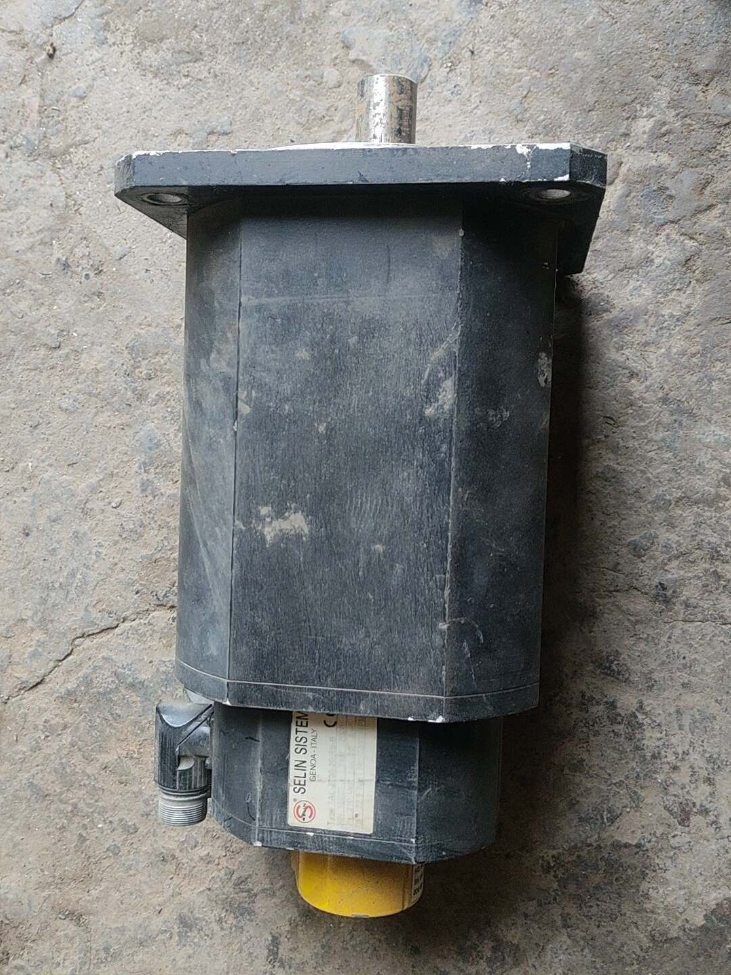
7AL-2700-20RS-B ist ein Allzweck-AC-Permanentmagnet-Synchronservomotor der Selin 7AL-Serie. Es ist werkseitig mit einem Resolver zur Signalrückführung und einer Power-Off-Bremse ausgestattet. Konzipiert als industrieller Servomotor mit mittlerer bis geringer Trägheit und hoher Zuverlässigkeit, Es eignet sich zur Positionierung und Drehmomentregelung in der Automobilkomponentenfertigung, Verpackungsmaschinen, Materialhandhabung und andere Bereiche.
- Interpretation des Modellcodes
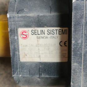
Modell: 7AL-2700-20RS-B
| Codesegment | Beschreibung | Basis |
| 7AL | Produktserie | Die AC-Servomotoren der 7. Generation der AL-Serie, die zentrale Allzweck-Servoproduktlinie des Herstellers. |
| 2700 | Nenndrehmoment | Einheit: mNm, gleichbedeutend mit 2.7 N*m. Diese Namenskonvention wird allgemein von europäischen Servoherstellern übernommen. |
| 20 | Bewerteter Geschwindigkeitscode | Entsprechende Nenngeschwindigkeit: 2000 U/min. Industriestandardregel: zwei Ziffern multipliziert mit 100 U/min. |
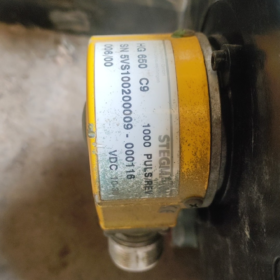
| RS | Feedback-Komponente | Steht für Resolver. Es zeichnet sich durch eine hervorragende Vibrationsfestigkeit aus, hohe Temperaturbeständigkeit und starke antielektromagnetische Interferenzfähigkeit, geeignet für raue Arbeitsbedingungen. |
| B | Konfigurationssuffix | Ausgestattet mit abschaltbarer elektromagnetischer Bremse. Die Abtriebswelle wird blockiert, sobald die Stromversorgung unterbrochen wird, Verhindert das Herabfallen vertikaler Lasten und behält die Position während des Herunterfahrens bei. |
- Grundlegende technische Spezifikationen
> Notiz: Die folgenden Parameter werden basierend auf allgemeinen Spezifikationen derselben Serie und Industriestandards abgeleitet. Die offiziellen Nennwerte entnehmen Sie bitte dem Metalltypenschild am Motorgehäuse.
3.1 Elektrische Leistung
| Parameter | Spezifikation | Bemerkungen |
| Motortyp | 3-Phase Permanentmagnet-Synchronservomotor | Sinuswellenbetrieb, Isolierung der Klasse F |
| Nenndrehmoment | 2.7 N·m | Kontinuierliche Betriebsbewertung |
| Spitzendrehmoment | Ca. 8.1 N·m | Kurzzeitüberlastfähigkeit, Standard 3 mal Überlastverhältnis |
| Nenngeschwindigkeit | 2000 U/min | Kontinuierliche Nennbetriebsgeschwindigkeit |
| Höchstgeschwindigkeit | Ca. 3000 U/min | Obergrenze der feldschwächenden Geschwindigkeitsregelung |
| Nennleistung | Ca. 0.565 kW | Berechnungsformel: P = T×n/9550 = 2,7×2000/9550 |
| Nennspannung | 3-Phase AC220V | Standard-Niederspannung für industrielle Servosysteme |
| Feedback-Typ | Resolver | Analoge Sinus-/Cosinus-Signalrückmeldung, anpassungsfähig an raue Umgebungen |
| Bremsspezifikation | Abschaltbare elektromagnetische Bremse | Nennspannung: DC24V; Statisches Haltemoment ≥ Nenndrehmoment |
| Isolationsklasse | Klasse F | Maximale Widerstandstemperatur der Wicklung: 155℃ |
3.2 Mechanisch & Montageparameter
| Parameter | Spezifikation | Bemerkungen |
| Flanschgröße | Standardmäßiger 80-mm-Vierkantflansch | Standard-80-mm-Rahmen für Motoren mit einem Drehmoment von 2 N·m zu 3 N·m |
| Abtriebswellendurchmesser | φ19mm mit paralleler Passfedernut | Standardwellendurchmesser für Industriemotoren mit 80-mm-Rahmen |
| Montageart | Flanschmontage, horizontal / Vertikaler Einbau möglich | Ausgestattet mit Zapfen zur Positionierung |
| Schutz vor Eindringen | IP65 (ohne Wellenverlängerung) | Staubdicht und spritzwassergeschützt, Geeignet für allgemeine Industriewerkstätten |
| Gewicht | Ca. 2.8~3,5 kg | Typisches Gewicht für Modelle mit Bremse |
| Kabelausgang | Direkter Kabeltyp | Drei unabhängige Kabel für die Stromversorgung, Resolver-Feedback bzw. Bremse |
3.3 Umgebungsparameter
| Parameter | Spezifikation |
| Betriebstemperatur | 0 ~ +40 ℃ (Kein Einfrieren oder Kondensieren) |
| Lagertemperatur | -20 ~ +80 ℃ |
| Vibrationsfestigkeit | 10~55Hz, Doppelamplitude 0,15 mm, X/Y/Z drei Achsen |
| Höhenbewertung | ≤1000m (Für größere Höhen ist eine Leistungsreduzierung erforderlich) |
- Passend & Auswahlhilfe
4.1 Kompatible Laufwerke
Es wird empfohlen, die passenden Servoantriebe von Selin Sistemleri zu verwenden. Der Antrieb muss das Resolver-Kommunikationsprotokoll unterstützen und für 0,75 kW ausgelegt sein. Wenn das Originallaufwerk nicht verfügbar ist, Alternativ können Allzweck-Servoantriebe mit Resolver-Unterstützung eingesetzt werden. Nach dem Austausch muss die automatische Abstimmung der Encoderphase abgeschlossen werden.
4.2 Methoden zur Parameterüberprüfung
- Überprüfen Sie das Metalltypenschild auf der Motorseite, um die Nennspannung zu bestätigen, Leistung, Drehmoment, Geschwindigkeit, Isolationsklasse und andere Nenndaten.
- Kabelsätze zählen: Motoren mit Bremse haben 3 Kabelsätze (Stromkabel, Resolver-Feedbackkabel, Bremskabel).
- Messen Sie den Abstand der Flanschbefestigungslöcher, Zapfendurchmesser und Wellendurchmesser, um die Montagekompatibilität zu überprüfen.
4.3 Alternative Modellempfehlungen
Wenn das Originalmodell eine lange Vorlaufzeit oder hohe Kosten hat, Gleichwertige Servomotoren mit identischen Einbaumaßen und Leistung werden wie folgt empfohlen:
| Marke | Modell | Kernparameter | Montagekompatibilität |
| Yaskawa | SGM7J-08AFC6E | 0.75kW, 2.39N*m, 3000U/min; anpassbar für 2000 U/min + Bremse + Resolver | Vollständig kompatibel mit 80-mm-Flansch |
| Delta | ECMA-C20807SS | 0.75kW, 2.39N*m, 3000U/min, mit Bremse | Identische Befestigungslöcher für 80-mm-Flansch |
| Innovation | ISMH1-75B30CB-U231Z | 0.75kW, 2.39N*m; anpassbar für Resolver + Bremse | Vollständig kompatibel mit 80-mm-Rahmen |
- Standardverdrahtungsdefinition
Allgemeine Verdrahtungsdefinition für 80-mm-Servomotor mit Resolver und Bremse (Die Kabelfarben können je nach Hersteller variieren. Vor der Verkabelung überprüfen).
| Kabelgruppe | Kernmarkierung | Funktion |
| Stromkabel | U, V, W | 3-Phasenleistungseingang |
| Stromkabel | PE (Grün-Gelb) | Schutzerde |
| Resolverkabel | R1, R2 | Erregerwicklung des Resolvers |
| Resolverkabel | S1, S2, S3, S4 | Sinus & Cosinus-Signalwicklungen |
| Resolverkabel | Schild | Einseitige Erdung zum Schutz vor elektromagnetischen Störungen |
| Bremskabel | BR+, BR- | Bremsleistungseingang, normalerweise DC24V |
- Typische Anwendungen
- Produktionslinien für Automobilkomponenten: Manipulatoren zum Be- und Entladen von Material in Stanzprozessen, Positionierung von Schweißvorrichtungen, Stationssteuerung an Förderstrecken. Die Rückmeldung des Resolvers passt sich den Werkstattbedingungen mit Vibrationen und Ölverschmutzung an.
- Vertikale Hebemechanismen: Z-Achsen-Module, Aufzüge und Stapler. Die Bremse verhindert das Absturz der Last bei Stromausfall.
- Verpackung & Druckmaschinen: Futterschächte, Spannungskontrolle und Schnittpositionierung. Das Design mit mittlerer bis niedriger Trägheit erfüllt die Anforderungen für häufiges Hochgeschwindigkeitsstarten und -stopps.
- Allgemeine Automatisierungsausrüstung: Hochpräzise Positionierung für Vorschubachsen von Werkzeugmaschinen, Textilmaschinen und Keramikmaschinen.
- Fehlerbehebungsmatrix
| Fehlerphänomen | Grundursache | Lösungen |
| Motor läuft nicht, Antrieb meldet Encoderfehler | 1. Loses oder gebrochenes Resolverkabel | 1. Schließen Sie den Feedback-Stecker wieder an und prüfen Sie den Kabeldurchgang |
| 2. Ungewöhnliche Erregerleistung für den Resolver | 2. Messen Sie die Erregerausgangsspannung des Antriebs | |
| 3. Nicht übereinstimmendes Encoder-Protokoll auf dem Antrieb | 3. Stellen Sie den Antriebsrückführungstyp auf Resolver ein | |
| Der Motor vibriert und erzeugt während des Betriebs ungewöhnliche Geräusche | 1. Nicht übereinstimmende Servoverstärkungsparameter | 1. Führen Sie eine automatische Verstärkungsoptimierung durch und reduzieren Sie die Steifigkeitsparameter |
| 2. Übermäßige Lastträgheit | 2. Berechnen Sie das Lastträgheitsverhältnis und verlängern Sie die Beschleunigungs-/Verzögerungszeit | |
| 3. Motorlager verschlissen | 3. Drehen Sie die Welle nach dem Ausschalten manuell, um sie auf Blockierungen und ungewöhnliche Geräusche zu prüfen | |
| Large positioning deviation | 1. Resolver signal affected by electromagnetic interference | 1. Single-end grounding for cable shield; route feedback cables separately from power cables |
| 2. Übermäßiges mechanisches Spiel | 2. Check backlash of lead screw and gear reducer and perform mechanical compensation | |
| 3. Incorrect electronic gear ratio setting | 3. Recalculate and reset electronic gear ratio | |
| Brake malfunction, shaft rotates freely | 1. Abnormal brake supply voltage | 1. Measure voltage across brake terminals to confirm normal DC24V supply |
| 2. Open circuit of brake coil | 2. Measure coil resistance to check for open circuit | |
| 3. Severe wear of friction plate | 3. Replace brake assembly if worn out | |
| Motor overheat alarm | 1. Continuous overload operation | 1. Reduce load or extend acceleration/deceleration time to avoid long-term overload |
| 2. Excessively high ambient temperature and poor heat dissipation | 2. Verbessern Sie die Belüftung und Wärmeableitung; Vermeiden Sie direkte Sonneneinstrahlung und eine geschlossene Installation | |
| 3. Falsche Stromparameter am Antrieb | 3. Motornennstrom prüfen und relevante Antriebsparameter korrigieren |
- Verbotene Operationen & Sicherheitsregeln
- Elektrische Regeln: Legen Sie keine Spannung über den Nennwert an. Verlegen Sie Leistungskabel und Feedbackkabel nicht im selben Kabelkanal. Stecken Sie Feedback-Anschlüsse nicht ein oder aus, wenn das Gerät eingeschaltet ist. Vertauschen Sie nicht die Polarität der Bremsleistung.
- Mechanische Regeln: Schlagen Sie nicht radial auf die Motorwelle. Betreiben Sie das Gerät nicht dauerhaft über dem Nenndrehmoment und der Nenndrehzahl. Wenden Sie keine radiale/axiale Belastung auf das Wellenende an, die den zulässigen Grenzwert überschreitet.
- Umweltregeln: Nicht in brennbaren Räumen verwenden, explosiver oder stark korrosiver Atmosphäre. Tauchen Sie den Motor nicht in Wasser und setzen Sie ihn nicht über längere Zeit direktem Wasserstrahl aus. Die Schaftverlängerung ist nicht wasserdicht.
- Bremsregeln: Betätigen Sie die Bremse nicht, während der Motor mit hoher Drehzahl läuft. Die Bremse dient nur zum statischen Halten nach dem Abschalten, nicht für dynamisches Bremsen.
- Inbetriebnahmeregeln: Nach dem Antriebsaustausch ist eine automatische Abstimmung der Resolverphase obligatorisch. Vor der Phasenkalibrierung ist der Hochgeschwindigkeitsbetrieb verboten, Andernfalls kann der Motor außer Kontrolle geraten und beschädigt werden.
Vollständige Modellliste & Einführung der Servomotoren der Serie 7AL von Selin Sistemleri
> Dokumenthinweis: Selin Sistemleri ist ein regionaler Hersteller industrieller Bewegungssteuerungen mit begrenzten öffentlich zugänglichen Gesamtkatalogen. Der folgende Inhalt wurde gemäß den einheitlichen Codierungsregeln der Marke und den allgemeinen Spezifikationsstandards für europäische Servomotoren zusammengestellt. Die Benennungsregel stimmt vollständig mit 7AL-2700-20RS-B überein, zur Modellüberprüfung und Ersatzreferenz. Die genauen Nennparameter finden Sie in den offiziellen Handbüchern oder auf den Typenschildern des Motors.
- Serienübersicht
Die 7AL-Serie ist Selins Kernlinie von 3-Phasen-Permanentmagnet-Synchron-AC-Servomotoren. Mit mittlerer bis geringer Trägheit und umfassender Kompatibilität, Der Leistungsbereich reicht von 0,05 kW bis 2,2 kW. Es stehen mehrere Feedback-Optionen zur Verfügung, inklusive Inkrementalgeber, Resolver und Absolutwertgeber, zusammen mit optionaler Ausschaltbremse. Diese Serie wird häufig in Verpackungsmaschinen eingesetzt, Materialtransport, Produktionslinien für Automobilkomponenten und allgemeine Automatisierungsgeräte.
- Einheitliche Benennungsregel
Festes Format: „7AL [Drehmomentcode] [Geschwindigkeitscode][Feedback-Code] [Konfigurationssuffix]`
| Codesegment | Regel | Definition optionaler Codes |
| 7AL | Fester Seriencode | Die Allzweck-Servomotorserie AL der 7. Generation |
| Drehmomentcode | 4 Ziffern, Einheit: mNm | Zeigt das Nenndrehmoment an, z.B. 2700 = 2.7 N·m |
| Geschwindigkeitscode | 2 Ziffern, Wert × 100 U/min | 15 = 1500 U/min; 20 = 2000 U/min; 30 = 3000 U/min |
| Feedback-Code | Briefe / Buchstabenkombinationen | E = Inkrementalgeber; RS = Resolver; AB = Absolutwertgeber |
| Konfigurationssuffix | Optional | Kein Zusatz = Ohne Bremse; B = Mit stromloser elektromagnetischer Bremse |
- Vollständige Modellliste
Klassifiziert nach Rahmengröße und Drehmomentklasse:
3.1 60mm Rahmen (Niedriger Drehmomentbereich)
| Vollständiges Modell | Nenndrehmoment | Nenngeschwindigkeit | Feedback-Typ | Bremse | Nennleistung (Berechnet) |
| 7AL-0400-30E | 0.4 N·m | 3000 U/min | Inkrementalgeber | NEIN | 0.126 kW |
| 7AL-0400-30E-B | 0.4 N·m | 3000 U/min | Inkrementalgeber | Ja | 0.126 kW |
| 7AL-0600-30E | 0.6 N·m | 3000 U/min | Inkrementalgeber | NEIN | 0.188 kW |
| 7AL-0600-30E-B | 0.6 N·m | 3000 U/min | Inkrementalgeber | Ja | 0.188 kW |
| 7AL-0900-20E | 0.9 N·m | 2000 U/min | Inkrementalgeber | NEIN | 0.188 kW |
| 7AL-0900-20RS | 0.9 N·m | 2000 U/min | Resolver | NEIN | 0.188 kW |
| 7AL-0900-20RS-B | 0.9 N·m | 2000 U/min | Resolver | Ja | 0.188 kW |
3.2 80mm Rahmen (Mittlerer Drehmomentbereich, Hauptmodelle)
| Vollständiges Modell | Nenndrehmoment | Nenngeschwindigkeit | Feedback-Typ | Bremse | Nennleistung (Berechnet) |
| 7AL-1300-30E | 1.3 N·m | 3000 U/min | Inkrementalgeber | NEIN | 0.408 kW |
| 7AL-1300-30E-B | 1.3 N·m | 3000 U/min | Inkrementalgeber | Ja | 0.408 kW |
| 7AL-2000-20E | 2.0 N·m | 2000 U/min | Inkrementalgeber | NEIN | 0.419 kW |
| 7AL-2000-20RS | 2.0 N·m | 2000 U/min | Resolver | NEIN | 0.419 kW |
| 7AL-2000-20RS-B | 2.0 N·m | 2000 U/min | Resolver | Ja | 0.419 kW |
| 7AL-2700-20RS-B | 2.7 N·m | 2000 U/min | Resolver | Ja | 0.565 kW |
| 7AL-2700-20E | 2.7 N·m | 2000 U/min | Inkrementalgeber | NEIN | 0.565 kW |
| 7AL-2700-20E-B | 2.7 N·m | 2000 U/min | Inkrementalgeber | Ja | 0.565 kW |
| 7AL-2700-15RS | 2.7 N·m | 1500 U/min | Resolver | NEIN | 0.424 kW |
3.3 90/110mm Rahmen (Hoher Drehmomentbereich)
| Vollständiges Modell | Nenndrehmoment | Nenngeschwindigkeit | Feedback-Typ | Bremse | Nennleistung (Berechnet) |
| 7AL-4000-20RS | 4.0 N*m | 2000 U/min | Resolver | NEIN | 0.838 kW |
| 7AL-4000-20RS-B | 4.0 N*m | 2000 U/min | Resolver | Ja | 0.838 kW |
| 7AL-5500-15RS | 5.5 N*m | 1500 U/min | Resolver | NEIN | 0.864 kW |
| 7AL-5500-15RS-B | 5.5 N*m | 1500 U/min | Resolver | Ja | 0.864 kW |
| 7AL-7200-15RS | 7.2 N*m | 1500 U/min | Resolver | NEIN | 1.131 kW |
| 7AL-7200-15RS-B | 7.2 N*m | 1500 U/min | Resolver | Ja | 1.131 kW |
- Passende Antriebsserie
Alle Servomotoren der Serie 7AL sind mit den Servoantrieben der Serie ASD-7A von Selin kompatibel, abgestimmt auf die Nennleistung:
0.1~0,2 kW: ASD-7A-0123
0.4~0,75 kW: ASD-7A-0423 / ASD-7A-0723
1.0~1,5 kW: ASD-7A-1023 / ASD-7A-1523
> Der Antrieb muss zum Motor-Feedback-Typ passen. Für Motoren mit Resolver sind Antriebe mit Resolver-Schnittstelle erforderlich. Bei Verwendung von Antrieben von Drittanbietern ist eine automatische Abstimmung der Encoderphase erforderlich.
- Modellverifizierungsmethoden
- Überprüfen Sie das Metalltypenschild am Motorgehäuse, um die Nennspannung zu bestätigen, Drehmoment, Geschwindigkeit, Feedback-Typ, Isolationsklasse und andere Parameter.
- Kabelsätze zählen: 3 Sets für Motoren mit Bremse (Stromkabel, Feedbackkabel, Bremskabel); 2 Sets für Modelle ohne Bremse.
- Flanschlochabstand messen, Zapfendurchmesser und Schaftdurchmesser zur Bestimmung der Rahmengröße: 60mm Rahmen = 60mm Flansch; 80mm Rahmen = 80mm Flansch; 90mm Rahmen = 90mm Flansch.

 Impuls-Heißsiegel-Temperaturregler")


 Relais")
")


NH42-63-318x560.png "Automatische Transferschalter vom Typ CHINT PC (ATS)NH42-63/4SZ")


