 Schütz,Leistungsschalter,Sensor,Encoder,SPS,Konverter

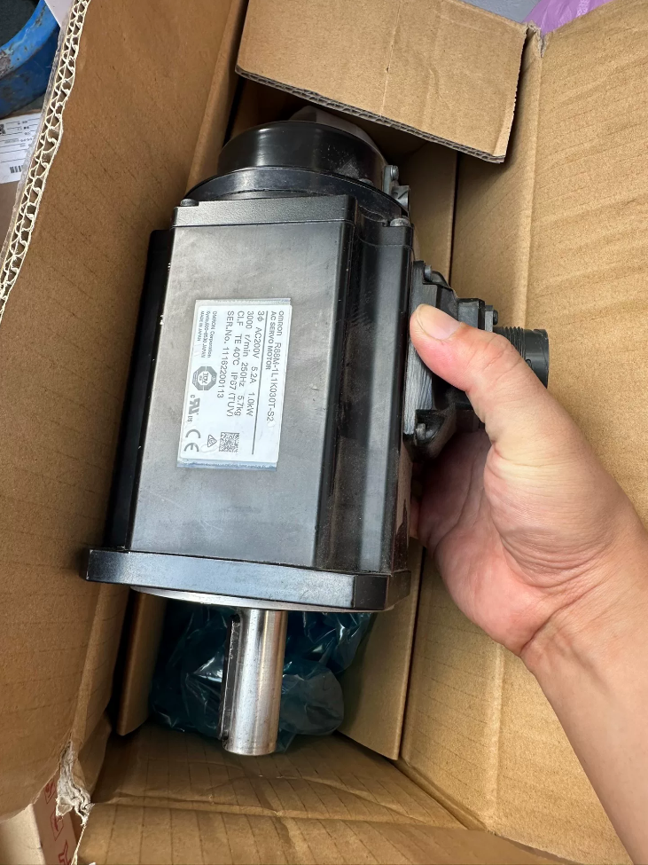

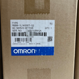
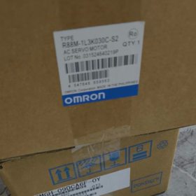
Serie: 1S Series Low-Inertia AC-Servomotor, compatible with EtherCAT bus servo drives, battery-free absolute encoder model
✅ Model Decoding
R88M-1L1K030T-S2
R88M: OMRON servo motor prefix
1: 1S Series
L: Low inertia motor
1K0: Rated power 1kW
30: Nenngeschwindigkeit 3000 U/min
T: 23-bit battery-free absolute encoder (ABS)
S2: Mit Keilnut + tapped hole on shaft end; keine Bremse, no oil seal
📋 Main Electrical Specifications
| Artikel | Parameter |
| Nennleistung | 1000 W (1kW) |
| Nenngeschwindigkeit | 3000 U/min |
| Maximale Geschwindigkeit | 5000 U/min |
| Nenndrehmoment | 3.18 N·m |
| Instantaneous Peak Torque | 9.55 N·m (3× Überlastung) |
| Nennstrom | 5.2 A (rms) |
| Spitzenstrom | 16.9 A (rms) |
| Encoder | 23-bit battery-free absolute encoder |
| Stromversorgung | Single-phase AC230V |
| Rotor Inertia | 4.2 ×10⁻⁴ kg·m² (ohne Bremse) |
| Allowable Load Inertia | Max. 42 ×10⁻⁴ kg·m² |
📐 Mechanical Specifications
Flansch: 100mm square flange
Schaftdurchmesser: φ19mm, with flat key + M5 tapped hole at shaft end
Gewicht: 5.7 kg
Bremse: No electromagnetic brake (brake model: R88M-1L1K030T-BS2)
Oil Seal: No oil seal (O suffix option for oil seal)
🔌 Matching Drive
Must be paired with OMRON 1S series EtherCAT servo drive:
R88D-1SN10F-ECT (einphasig 230V, 1kW EtherCAT drive)
🧩 Typical Applications
EtherCAT bus equipment: automated assembly lines, CNC, laser equipment, handling manipulators, high-speed positioning platforms, Verpackungsmaschinen. Low inertia design suitable for frequent start-stop and fast response motion control.
⚠️ Key Features
- Battery-free absolute encoder: Position retention at power-off, no battery maintenance, eliminates risk of origin loss caused by battery failure
- EtherCAT bus, high-speed synchronization for multi-axis coordination
- 3× short-time overload capability to handle impact loads
- Low inertia rotor for excellent dynamic response
📌 Related Model Selection Reference
R88M-1L1K030H-S2: 1kW, 3000U/min, Inkrementalgeber, mit Keilnut
R88M-1L1K030T-BS2: 1kW, 3000U/min, Absolutwertgeber, with 24V brake
R88M-1L1K030T-OS2: 1kW, 3000U/min, Absolutwertgeber, with oil seal + Keilnut
📎 Matching Cable Part Numbers
Stromkabel: R88A-CA1G□□□
Encoderkabel: R88A-CR1G□□□
Troubleshooting Checklist for OMRON 1S Servo R88M-1L1K030T-S2 + R88D-1SN10F-ECT
Voraussetzung: Motor equipped with 23-bit battery-free absolute encoder, keine Bremse; EtherCAT bus drive with STO safety terminals. ⚠️ Insulation test (megger) must be performed with motor disconnected from drive. Never apply high voltage/megger test while drive is connected; power module will be burned out directly.
- Pre-power-on Basic Inspection (Power OFF)
- Mechanical Check
Manually turn motor shaft: smooth rotation without jamming or metal friction noise; seizure = bearing damage / mechanical load stuck
Tighten flange and coupling screws; excessive misalignment causes vibration and overload
Verify load inertia: maximum allowable load inertia 42×10⁻⁴ kg·m², excess will lead to oscillation and overload alarms
- Kabel & Connectors
Power cable U/V/W/PE: check for outer sheath damage, loose or oxidized pins; measure phase resistance with multimeter, three-phase resistance should be balanced; confirm no short circuit between U/V/W and ground
Encoderkabel: secure connectors, shield grounded at drive side only; do not bundle encoder cables in parallel with power cables (interference source)
EtherCAT cable: intact RJ45 connector, verify OP state; follow IN/OUT sequence for multi-axis systems
- Stromkreis
Single-phase AC230V input, voltage range 180~264VAC; check circuit breaker and contactor contacts
Reliable PE grounding, common ground for drive and motor; poor grounding easily triggers encoder communication alarms
- Power ON, No Alarm, but Servo Cannot Enable (SON cannot turn ON)
- Check STO safety terminals: STO1/STO2 must be short-circuited. Disconnected STO prevents servo ON and triggers safety-related alarms
- EtherCAT Status: confirm bus enters OP state; INIT/PREOP means communication failure, controller cannot send enable commands
- Drive Input Terminals: check if ESTP emergency stop is triggered; limit switch logic
- Controller Program: MC_Power instruction, axis enable logic, axis configuration (matched motor model)
- Parameterüberprüfung: motor code, encoder type must be set to Battery-free ABS
- Main Drive Alarm Code Troubleshooting
| Alarmcode | Alarm Name | Punkte zur Fehlerbehebung |
| 1 | Überstrom | U/V/W short circuit or earth fault; motor coil insulation damage; drive power module failure; wrong phase sequence; noise false alarm |
| 12 | Motor Overheat | Ständige Überlastung; hohe Umgebungstemperatur; poor motor heat dissipation; broken motor temperature sensor |
| 13 | Main Circuit Undervoltage | Low AC230V input; voltage drop at power-up; insufficient power capacity; blown main circuit fuse |
| 14.00/14.01/14.02 | Regeneration Fault / Regeneration Overload | Excessively fast deceleration; broken/wrong resistance value of external regenerative resistor; excessive load inertia; insufficient power supply capacity |
| 16 | Drive Overheat | Blocked drive fan; poor cabinet heat dissipation; long-time overload |
| 21 | Encoder Communication Disconnect | Loose encoder plug, Kabelbruch; abnormal encoder power supply; damaged pin; cable interference |
| 21.01 | Encoder Communication Error | Schlechte Schirmerdung, power cable interference; internal encoder fault; overlong cable |
| 24 | Position Deviation Excess | Mechanischer Stau, heavy load; low gain; too short acceleration/deceleration time; slipping coupling; abnormal command pulse |
| 24.01 | Speed Deviation Excess | Mechanical binding; torque saturation; mismatched gain |
| 26 | Overspeed | Incorrect electronic gear ratio; abnormal command; load inertia pulling motor runaway; high gain induced oscillation |
| 27.01 | Absolute Value Clear (Battery-free ABS) | Home origin setup for first use; shaft rotated by external force while powered off; internal encoder fault, home reset required |
| 87 | External Emergency Stop ESTP | Emergency stop circuit open, check E-stop button and wiring |
- Abnormal Motor Operation (No Alarm or Minor Warning)
4.1 Motor Shaking, Ungewöhnliches Geräusch, Vibration
Mechanisch: coupling misalignment, mechanical backlash, load resonance
Kontrolle: übermäßiger Gewinn; inertia identification not completed; improper acceleration/deceleration setting
Elektrisch: encoder interference; unbalanced three-phase current; poor contact of power cable
4.2 Severe Motor Heating
Continuous load exceeds rated torque; frequent start-stop; hohe Umgebungstemperatur
Current Monitoring: monitor motor current via drive; continuous current near rated 5.2A indicates heavy load
4.3 Poor Positioning Accuracy, Origin Loss (Battery-free ABS model)
R88M-1L1K030T-S2: Battery-free absolute encoder. Position is retained if shaft stays stationary at power-off. Origin will be lost and 27.01 alarm triggered if shaft is rotated by external force during power-off.
Check encoder cable shield; loose connector caused by vibration
Mechanical backlash, slipping coupling
If shaft is rotated externally after every power cut → home return required every power-up
- EtherCAT Communication Faults
- Bus stuck at PREOP: beschädigtes Kabel, wrong wiring sequence, incorrect slave ID; Nicht übereinstimmende Firmware-Version des Laufwerks
- Intermittent bus disconnection during operation: poor cable shielding; power cable interference; power noise; loose RJ45 connector
- Occasional PDO frame loss: reduce bus cycle time; extend communication watchdog time; optimize grounding
- Isolation Test Method (Quickly Locate Fault: Motor / Kabel / Fahren)
- Separate Motor and Drive Test
Disconnect power cable and encoder cable; power on drive alone. If alarm disappears → fault in motor/cable; if alarm persists → drive hardware failure
- Cross Swap Test (Same-axis model)
Swap motor + encoder cable to a healthy drive, judge whether fault source is motor or drive
- Motor Coil Test
Power OFF, measure U/V/W phase resistance with multimeter. Resistance difference between three phases <5%; conduction between any phase and PE = motor shorted to ground
❗ Do NOT use megger on encoder circuit, encoder chip will be destroyed
- Periodic Maintenance Checklist
- Monatlich: Tighten connectors, inspect cable wear; clean fan dust
- Vierteljährlich: Check motor bearing noise; retighten coupling and mechanical screws
- Jährlich: Inspect grounding and shielding integrity; record motor temperature rise; back up drive firmware
- Battery-free ABS model: Regularly verify home origin logic to avoid origin loss caused by external shaft rotation at power-off
- Sicherheitshinweise
Main circuit capacitor retains high voltage after power-off, wait ≥5 minutes before disconnecting wiring
Do NOT perform insulation resistance test (megger) with drive connected
Do NOT touch rotating shaft while servo is ON to prevent mechanical injury
Parameter Setting Guide for OMRON 1S Servo R88M-1L1K030T-S2 + R88D-1SN10F-ECT (Sysmac Studio, NX/NJ Controller)
Motor: 23-bit battery-free absolute encoder, keine Bremse; EtherCAT bus drive, STO safety terminals must be short-circuited, otherwise servo ON is unavailable.
Encoder resolution per revolution: 8388608 counts/rev
Vorbereitungen
- Hardware Wiring: Power cable U/V/W/PE, Encoderkabel, EtherCAT cable, short STO1/STO2, ESTP emergency stop wiring;
- Install Sysmac Studio on PC, connect NX/NJ controller via USB;
- Pre-power inspection: shaft can be rotated manually without jamming, AC230V power supply normal, zuverlässige Erdung;
- Create new project in controller, select corresponding NX/NJ CPU.
- Scan EtherCAT Bus and Identify Servo Drive
- [Configuration and Setup] → [EtherCAT], right-click EtherCAT Master → Compare and Merge with Actual Network
- Software automatically scans EtherCAT slaves and recognizes R88D-1SN10F-ECT drive;
- Confirm drive node address, klicken [Anwenden], bus state becomes PREOP;
Stuck at INIT: defektes Kabel / wrong node address; PREOP is normal, bus enters OP after project download.
- Right-click drive → Assign Drive to Axis, motion axis (Axis0) generated automatically.
- Drive Quick Setup Wizard (Kritisch!)
Right-click R88D-1SN10F-ECT drive → Setup and Tuning → Quick Parameter Setup and I/O Monitor
- Motor & Encoder Setting (Key for this model)
Motormodell: R88M-1L1K030T-S2, software auto-load matching parameters;
Encodertyp: Battery-free Absolute Encoder
Absolute Mode Option: Use Absolute Encoder, Ignore Multi-turn Overflow (Empfohlen)
For first use, Motoraustausch, corrupted multi-turn encoder data: klicken [Clear System], drive restarts to clear multi-turn data. Alarm 27.01 will pop up, this is normal.
- I/O Terminal Setting
STO: Hardwired short;
ESTP external emergency stop: connect E-stop button; IN1 can be disabled in software if unused;
POT/NOT limit switches, DEC home sensor: enable as required; disable in software if not wired.
- Motor Rotation Direction Test
Klicken [Servo ON], use JOG to test rotation direction;
Rückwärtsdrehung: tick [Reverse Motor Rotation Direction], download parameters to drive;
- Save parameters to drive EEPROM.
- Motion Axis Parameter Configuration (Unit Conversion / Elektronische Ausrüstung)
Double-click generated motion axis Axis0 → [Axis Parameters]
Encoder count per revolution: 8388608 pulse/rev
Fall 1: Ball Screw (Screw lead 5mm, reduction ratio 1:1)
1 motor revolution → worktable moves 5mm
Command count per motor revolution: 8388608
Travel distance per motor revolution: 5 mm
Einheit: mm
Bedeutung: 8388608 encoder pulses of motor correspond to 5mm mechanical displacement. System calculates electronic gear automatically. For 1S bus servo, do NOT fill electronic gear manually, set mechanical travel directly.
Fall 2: Rotary Axis, motor directly connected to turntable, 1 rev = 360°
Travel distance per motor revolution: 360 deg
Einheit: degree
Axis Limit Parameters
Maximale Geschwindigkeit: motor rated speed 3000rpm, convert to corresponding mechanical speed;
Acceleration/Deceleration: set longer time (0.2~0.5s) at initial commissioning, shorten after tuning;
Soft Limit: aktivieren, set positive and negative soft limit values;
Home Setting (Battery-free ABS)
✅ Battery-free absolute encoder: current position can be read at normal power-up, no mandatory home return every power-on; if shaft is rotated by external force during power-off, origin is lost and 27.01 alarm triggered, home calibration required
Home Mode: [Absolute Origin Preset], set mechanical zero position as origin;
If external home sensor is used: select home search mode (reverse near / home input).
- Servo Gain Auto-tuning (Easy Tuning, Recommended for Beginners)
Right-click drive → Setup and Tuning → Easy Tuning
- Select tuning mode: Simple mode;
- Select mechanical type: Ball screw / Gürtel / Direct drive;
Ball screw: relatively high rigidity; Gürtel: low rigidity;
- Set JOG travel and speed;
- Click Start, drive runs reciprocally automatically, identifies load inertia and generates position loop gain, speed loop gain and filter automatically;
- Save gain parameters to drive EEPROM after tuning;
If simple tuning is insufficient, verwenden [Advanced Auto-Tuning] or manually modify [Mechanical Rigidness 0~31]. Higher value = higher gain and faster response, excessive value causes vibration and squeal
Experience: Ball screw 8~16; Belt mechanism 3~8.
- Important Drive Parameter List
| Parameterelement | Beschreibung & Reference Value for this Model |
| Motorcode | R88M-1L1K030T-S2, auto-written by wizard, DO NOT modify manually |
| Encoder Mode | Battery-free ABS |
| Torque Limit | Standard 300% (3脳 overload), can be reduced to prevent collision |
| Regenerative Resistor | Built-in regeneration for light load; external regenerative resistor required for frequent fast deceleration & large inertia load |
| Communication Cycle | Recommended EtherCAT bus cycle 500渭s / 250渭s, unified cycle for multi-axis synchronization |
| Vibration Suppression Filter | Enabled automatically after auto-tuning; notch filter can be manually enabled for mechanical resonance |
- Download Project and Commissioning Procedure
- Save project, download project to NX/NJ controller;
- Write drive parameters into EEPROM (prevent parameter loss after power-off);
- Monitor screen: check axis status, actual position, motor current, bus OP state;
- Program use MC_Power to enable servo; MC_MoveAbsolute / MC_MoveRelative for positioning;
- JOG test run, check: rotation direction, abnormal vibration/noise, positioning performance;
- Home Calibration: move mechanism to mechanical zero position, execute [Set Current Position as Origin].
- Allgemeine Alarme & Parameter-related Faults
- 27.01 Absolute Value Clear: Shaft rotated by external force while powered off, multi-turn encoder data lost; re-run Clear System and calibrate origin;
- 87.00 ESTP Emergency Stop Alarm: Emergency stop circuit open, check IN1 wiring or disable E-stop in software;
- STO-related Alarms: STO1/STO2 not short-circuited, safety circuit open, servo cannot enable;
- 21.00 Encoder Cable Breakage: Loose encoder cable, oxidierte Stifte, poor shield grounding;
- Motor Shaking: Excessive gain, reduce mechanical rigidness and re-run auto-tuning;
- Poor Position Deviation: Incorrect unit conversion parameter, uncompensated backlash, slipping coupling.
- Wichtige Hinweise
- Nach Parameteränderung, must save to drive EEPROM, parameters will not be retained after drive power-off otherwise;
- Battery-free ABS: position is retained if shaft remains stationary at power-off; origin lost if shaft is rotated externally during power-off;
- Reduce torque limit during commissioning to prevent mechanical collision damage;
- Bus servo, no manual calculation and entry of electronic gear ratio, Satz [Travel Distance per Revolution] in axis parameters;
- Drive must be restarted after modifying motor model or encoder type for changes to take effect.



NH42-63-318x560.png "Automatische Transferschalter vom Typ CHINT PC (ATS)NH42-63/4SZ")



