 Schütz,Leistungsschalter,Sensor,Encoder,SPS,Konverter

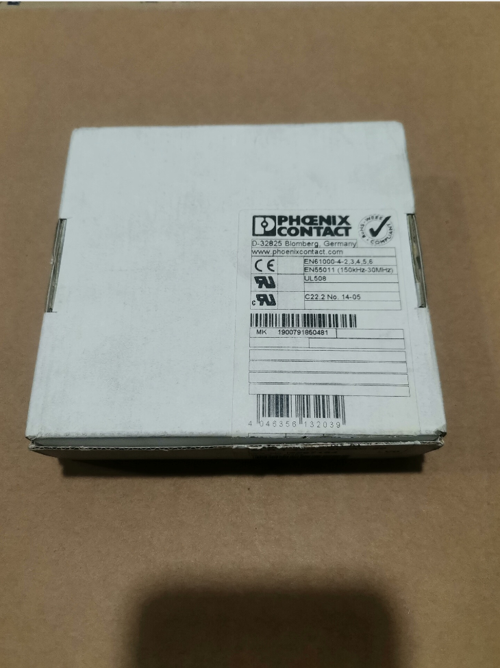

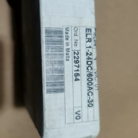
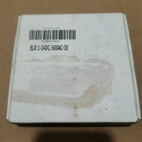
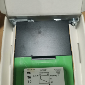
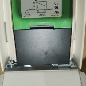
Phoenix Contact ELR1-24DC-600AC-30, Bestell-Nr. 2297154
- Vollständige Modelldekodierung
Modell: ELR1-24DC-600AC-30
- ELR1: Serie → ELR1 einphasig
- 1 einphasige elektronische Last Relais
- (Halbleiterschütz, kontaktloser Schalter, Geeignet für Motorlasten)
- 24Gleichstrom: Steuerseitige Versorgung / Antriebsspannung: 24 In DC
- 600Wechselstrom: Bemessungsbetriebsspannung des Hauptstromkreises: Wechselstrom 0…600 V
- 30: Bemessungsdauerbetriebsstrom: 30 A
- 2297154: Offizielles Unikat Phönix Bestellnummer kontaktieren
Vollständiger Produktname: ELR 1-24DC/600AC-30 Halbleiterschütz
- Elektrische Kernparameter
| Artikel | Spezifikation |
| Bestell-Nr. | 2297154 |
| Steuerspannung | 24 In DC (zulässigen Bereich: 19.2~30V DC) |
| Hauptstromkreisspannung | Wechselstrom 0–600 V, 50/60 Hz |
| Nennlaststrom | 30 A (ohmsche Last) |
| Anwendbarer Lasttyp | Einphasige Wechselstromlasten; Fans, Heizelemente, kleine Einphasenmotoren |
| Schaltkomponente | Bidirektionaler Triac (kontaktlos) |
| Schaltfrequenz | Viel höher als bei mechanischen Schützen, Geeignet für häufiges Schalten |
| Isolierung | Optoelektronische Isolierung; galvanische Trennung zwischen Steuerstromkreis und Hauptstromkreis |
| Montageart | 35 mm DIN-Schienenmontage |
| Verbindung | Schraubklemmenanschluss |
| Umgebungstemperatur | -20 ℃ ~ +60 ℃ (Die oben erforderliche Leistungsreduzierung ist erforderlich 40 ℃) |
- Hauptmerkmale
✅ Keine mechanischen Kontakte, keine Lichtbögen, geräuscharm, verlängerte Lebensdauer, Ideal für häufigen Start-Stopp-Betrieb
✅ Eingebauter Überspannungsabsorptionsschaltkreis zur Unterdrückung induktiver Laststöße
⚠️ Wichtige Einschränkung: Einphasiges Halbleiterrelais. Nicht zur direkten Ansteuerung von Drehstromlasten geeignet; Gilt nur für einphasige Wechselstromlasten
⚠️ Für induktive Lasten (Motoren, Spulen), Es ist eine ausreichende aktuelle Marge erforderlich; 30% Eine Stromreduzierung wird empfohlen
- Stift / Terminaldefinition
A1 / A2: Steuerklemmen für 24 In DC
A1(+), A2(-)
L / N: AC-Eingangsklemmen des Hauptstromkreises
AUS: Ausgangsterminal laden
- Typische Anwendungsszenarien
Steuerung von Elektroheizungen in industriellen Schaltschränken
Häufiges Starten und Stoppen von einphasigen Ventilatoren und Fördermotoren
Temperaturregelkreise für Verpackungsmaschinen, Prüfgeräte und Öfen
Wechselstromlasten, die eine geringe Geräuschentwicklung erfordern, wartungsfreies Schalten
- Alternative & Referenzen zur gleichen Serie
- Stromärmere Varianten derselben Serie: ELR1-24DC-600AC-10 (10 A), ELR1-24DC-600AC-20 (20 A)
- Für dreiphasige Halbleiterschalter: Siehe ELR3-Serie (dreiphasige Halbleiterschütze)
- Mitbewerberäquivalente: Schneider SSP-Serie, Omron G3PA einphasige Halbleiterrelais
- Beschaffungshinweise
Unterscheiden Sie Modellsuffixe: Verwechseln Sie ELR1 nicht (einphasig) / ELR3 (dreiphasig)
Bestellnummer verwenden 2297154 Es ist unbedingt zu vermeiden, dass andere aktuelle Bewertungen übermittelt werden
Festkörperkomponenten erzeugen erhebliche Wärme; Bei dichtem Einbau in Schaltschränken ist ausreichend Freiraum zur Wärmeableitung erforderlich
Anwendungsszenarien – Phoenix Contact ELR 1-24DC/600AC-30 (Bestellnr.2297154)
Zusammenfassung der Produktübersicht
Einphasiger Halbleiterschütz (kontaktloses SSR)
Kontrolle: 24 In DC; Hauptstromkreis: ≤600 V Wechselstrom, bewertet 30 A; DIN-Schienenmontage; optoelektronische Isolierung; bidirektionaler Triac-Ausgang; optimiert für häufiges Schalten von einphasigen Wechselstromlasten
Kernvorteile: Lichtbogenfrei, kein mechanischer Verschleiß, geräuscharm, schnelles häufiges Umschalten. Einschränkung: Selbsterwärmung, Stromreduzierung für induktive Lasten obligatorisch.
Kritische Prämisse: Unterstützt nur einphasige Wechselstromlasten; kann Drehstrommotoren nicht direkt antreiben
- Allgemeine Standard-Industrieszenarien
1.1 Widerstandsheizlasten (Häufigste Anwendung)
- Steuerung von Heizrohren in Öfen, Tunnelöfen und thermische Verarbeitungsanlagen
- Heizkreise für Spritzguss- und Extruderzylinder
- Industriethermostate, Heißluftgebläse und elektrische Kanalheizungen
- Heizelemente von Heißsiegelmaschinen und Heißprägegeräten in Verpackungsmaschinen
✅ Vorteil: PID-Hochfrequenz-Kontinuierliches Schalten durch Temperaturregler verschleißt schnell die Kontakte mechanischer Schütze; ELR1 passt perfekt zu diesem Betriebszustand
1.2 Einphasenventilatoren & Pumps (Induktive Lasten)
Bewerbungsvoraussetzung: 25%~30 % Stromreduzierung für die Lastauswahl
- Kühlventilatoren für Schaltschränke, Industrie-Abluftventilatoren und einphasige Kanalventilatoren
- Kleine einphasige Kreiselpumpen, Umwälzpumpen und Rauchabzugsventilatoren
- Luftversorgungseinheiten für Trocknungsgeräte
⚠️ Hinweis: Großer Einschaltstrom beim Motorstart; recommended actual load ≤20~22 A for the 30 Ein Modell
1.3 Lighting Loads
- High-power halogen lamp banks and infrared heating lamp arrays in workshops
- High-power lighting arrays in test laboratories
❌ Nicht empfohlen: LED drivers and electronic ballast loads (hoher Einschaltstrom; RC snubber circuit is recommended)
- Industry-Specific Field Applications
▶ Packaging Machinery
- Heating control for heat shrink tunnels
- Actuation of heat-seal bars on vertical / horizontale Verpackungsmaschinen
- Single-phase drive motors on conveying lines and hot air drying systems
▶ Plastics & Gummimaschinen
- Heating rod control for each temperature zone of extruders and pelletizers
- Start-stop control of heating circuits for mold temperature controllers
▶ HVAC & Environmental Test Equipment
- Heaters for high-low temperature test chambers and constant temperature & humidity chambers
- Heißluftzirkulationssysteme für Reinigungsgeräte
- Heizmodule von industriellen Luftentfeuchtern
▶ Neue Energie & Produktionslinien für Lithiumbatterien
- Heizungssteuerung für Elektroden-Trockenöfen
- Heißluftgeräte für Staubentfernungsgeräte
Vorteil: Kein Funkenflug für staubfreie Werkstätten (Das Gerät selbst ist NICHT explosionsgeschützt; Für explosionsgefährdete Bereiche ist eine explosionsgeschützte Kapselung zwingend erforderlich)
▶ Essen & Pharmazeutische Ausrüstung
- Elektrische Heizsysteme für Lebensmittelbacklinien und Sterilisationsgeräte
- Heißlufttrocknungsgeräte für Reinigungsgeräte
Vorteil: Der berührungslose Betrieb verhindert die Entstehung von metallischem Staub, Erfüllung der Betriebsanforderungen für Reinräume
▶ Automatisierte Testgeräte
- Schalten von Hochleistungslasten auf in die Jahre gekommenen Prüfständen
- Einstellbare AC-Lastschaltgeräte in Laboren
- Clustersteuerung von Hochleistungs-Wechselstrom-Magnetspulen
- Nicht anwendbare Szenarien (Auswahl roter Linien)
- ❌ Direkte Ansteuerung von Drehstrom-Asynchronmotoren (ELR1 ist ein einphasiges SSR; steuert nur eine Phase. Als dreiphasiger Hauptschalter strengstens verboten. Wählen Sie die ELR3-Serie für dreiphasige Lasten)
- ❌ Häufiges Anlaufen von Hochleistungs-Einphasenkompressoren (Ein starker Einschaltstromstoß kann zum Ausfall des Triacs führen)
- ❌ Anwendungen, bei denen das Gerät langfristig überlastet ist & Kurzschlussschutz (Halbleiterrelais haben eine schlechte Kurzschlussfestigkeit; Leistungsschalter / Sicherungen müssen vorgeschaltet sein)
- ❌ Ungeschützte Freiluftaufstellung im Freien (müssen in Schaltschränken eingebaut werden)
- ❌ Induktive Hochfrequenz-Hochspannungslasten ohne RC-Überspannungsschutzschaltungen
- Empfohlene unterstützende Konfiguration für die Bereitstellung vor Ort
- Induktive Lasten (Motoren, Spulen): Parallele RC-Absorptionsmodule von Phoenix Contact zur Unterdrückung von Gegen-EMF
- Mehrere Einheiten nebeneinander auf DIN-Schiene montiert: Halten Sie einen Mindestabstand von ≥10 mm zwischen benachbarten Geräten ein; Stromreduzierung erforderlich, wenn die Umgebungstemperatur des Schranks > 45 °C beträgt
- Upstream-Schutz: Setzen Sie gG-Sicherungen ein; Leistungsschalter allein können keinen zuverlässigen Kurzschlussschutz bieten
- Bevorzugte Komponente für PID-Temperaturregelsysteme; Die Schaltfrequenz kann mehrere Zyklen pro Sekunde erreichen, Lebensdauer, die weit über der von mechanischen Schützen liegt
Montagespezifikation – Phoenix Contact ELR 1-24DC/600AC-30 (2297154)
- Standard-Montageform
Standardmontage: Snap-on-Installation an 35 mm DIN-Schiene (TH35-7,5)
- Integrierter DIN-Schienen-Verriegelungsclip auf der Geräterückseite; keine zusätzlichen Halterungen erforderlich
- Obligatorische Montageausrichtung: Vertikale Installation (Die Anschlüsse müssen nach oben/unten zeigen; Kühlrippen vertikal angeordnet)
❌ Horizontale Seitenmontage & umgekehrter Einbau ist verboten! Durch die horizontale Platzierung wird die natürliche Konvektionskühlung blockiert, Dies führt zu einer Überhitzungsabschaltung und einer Beschädigung des Triacs.
- Montage & Demontageverfahren
- Hängen Sie den oberen Clip in die DIN-Schiene ein;
- Drücken Sie den Hauptkörper nach unten, bis ein hörbares Geräusch ertönt “klicken” bestätigt, dass der untere Clip an der Schiene einrastet;
- Entfernung: Öffnen Sie den unteren Clip mit einem flachen Schraubendreher und heben Sie das Gerät nach oben.
- Anforderungen an den thermischen Abstand (Kritisch! 30 Ein Halbleiterschütz erzeugt erhebliche Wärme)
Einzelne unabhängige Installation
Vertikaler Abstand (Spitze & unten): ≥50 mm Belüftungsraum
Seitlicher Spielraum: ≥10 mm, wenn angrenzender Raum frei ist
Mehrere Einheiten nebeneinander auf derselben DIN-Schiene montiert
Mindestabstand zwischen benachbarten Geräten: ≥10 mm
Eine spielfrei dichte Anordnung ist verboten
Halten Sie einen Abstand von ≥15 mm ein, wenn die Schranktemperatur >40 °C beträgt
Für großflächige Dauerinstallationen, Es wird eine Zwangsluftkühlung über Gehäuse-Axialventilatoren empfohlen
- Verkabelungsspezifikation (Schraubklemmen)
Anschlussbelegung
A1(+), A2(-): 24 V DC-Steuerkreis
L, AUS: Hauptstromkreis für einphasige Wechselstromlasten
Verdrahtungsparameter
- Terminaltyp: Schraubklemmen gegen Lösen
- Anwendbare Leiter:
Massiver einadriger Draht: 0.5~10 mm²
Flexibler Litzendraht: Crimplaschen werden empfohlen
- Empfohlenes Anzugsdrehmoment: 1.2~1,5 N·m
⚠️ Unzureichendes Drehmoment → übermäßige Erwärmung; Übermäßiges Drehmoment → Gewindedurchrutschen oder Rissbildung am Anschlusssockel.
Vorschlag für die Verkabelungsanordnung
Separate Führung für Steuerkabel (A1/A2) und Hochleistungskabel (LÜMMEL) um elektromagnetische Störungen zu reduzieren
Minimieren Sie die Länge der Stromkabel, um Spannungsabfall und Wärmeentwicklung zu reduzieren
- Umgebungsbedingungen für den Betrieb
- Installationsort: In Schaltschränken, Schutzklasse IP20
❌ Direkte Exposition gegenüber der frischen Luft; Staub vermeiden, Feuchtigkeit und Kondenswasser dürfen nicht mit dem Gerät in Kontakt kommen
- Zulässige Betriebstemperatur: -20 ℃ ~ +60 ℃
Bei einer Umgebungstemperatur > 40 °C ist eine Stromreduzierung erforderlich
- Vermeiden Sie diese Einbaulagen:
Direkt über Transformatoren, Leistungswiderstände und andere wärmeerzeugende Bauteile
Schlecht belüftete Totzonen in Schränken
Standorte mit anhaltend starken Vibrationen (Kontinuierliche Vibration löst die Klemmschrauben)
- Optionales Wärmeableitungszubehör
Für den dauerhaften Volllastbetrieb in geschlossenen Schränken, Zur Reduzierung der Gehäusetemperatur können auf der Rückseite des Geräts auf DIN-Schienen montierte Aluminium-Kühlkörper angebracht werden.
Standardmäßig wird kein Kühlkörper mitgeliefert; Die Kühlung erfolgt über integrierte Gehäuserippen für natürliche Konvektion.
- Streng verbotene Operationen
- Hängen Sie das Gerät nicht an Kabeln auf; Die gesamte mechanische Belastung muss von der DIN-Schiene getragen werden
- Blockieren Sie nicht die Kühlrippen an den Seiten und an der Rückseite
- Schließen Sie zur Stromaufteilung nicht mehrere ELR1-Einheiten parallel an (Ein inkonsistenter Einschaltwiderstand führt zu einer ungleichmäßigen Stromverteilung und einem Durchbrennen)
- Installieren Sie keine Schütze / Leistungsschalter dicht neben Halbleiterschützen ohne Wärmeabstände
Standardbeschreibung für technische Zeichnungen
Der ELR1-24DC/600AC-30 muss vertikal auf einer TH35-Standard-DIN-Schiene montiert werden. Seitlicher Abstand zwischen benachbarten Geräten ≥10 mm. Getrennte Führung für Steuer- und Stromkreise. Anzugsdrehmoment der Klemmen: 1.2~1,5 N·m. Sorgen Sie für eine ausreichende natürliche Belüftung zur Wärmeableitung.



NH42-63-318x560.png "Automatische Transferschalter vom Typ CHINT PC (ATS)NH42-63/4SZ")



