 Schütz,Leistungsschalter,Sensor,Encoder,SPS,Konverter

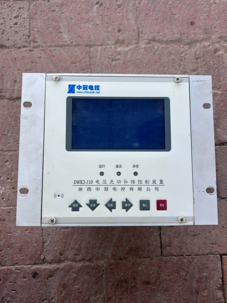

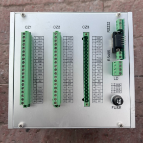
DWK3-110 is a substation voltage and reactive power integrated Regler (VQC), commonly known as high-voltage reactive power compensation controller. It is used in 6~110kV substations to automatically regulate busbar voltage and switch capacitor/reactor banks, realizing integrated optimal control of voltage and reactive power. It is widely applied in power grid substations and distribution station high-voltage reactive power compensation cubicles.
✅ Model Nomenclature & Unterserie
DWK3-110【Suffix】
Serie A (Integrated VQC: main transformer voltage regulation + capacitor switching)
DWK3-110A2: 1~2 main transformers, 1~2 capacitor banks
DWK3-110A8: 1~2 main transformers, 1~8 capacitor banks
DWK3-110A36: 1~3 main transformers, 1~6 capacitor/reactor banks, supports three-section busbar
Serie C (Pure high-voltage reactive compensation, capacitor switching only, no main transformer voltage regulation)
DWK3-110CD: Simple single-busbar type, controls 1~4 capacitor banks (commonly used for 6/10kV)
DWK3-110C4D / C8D / C12 / C38: Einzel / doppelt / three-section busbar, 4/8/12 Kondensatorbänke
Series T (Regulating reactive power compensation, patented solution, on-load tap-changer capacitor): DWK3-110TC1, TC2, TA2
Series L (Special for filter compensation): DWK3-110LD, L8, L12, for filter capacitor bank switching control
Series D: Low-voltage reactive power compensation; Serie B: Capacitor bank protection device
✅ Core Functions
- Steuerlogik: Real-time acquisition of busbar U, ICH, P, Q, cosφ; automatic switching of capacitors/reactors based on dual criteria of voltage and reactive power. Series A additionally controls on-load tap positions of main transformers, with anti-tap hunting and anti-switching oscillation functions.
- Switching Strategy: Supports equal-capacity balanced switching, unequal-capacity selective switching and combined switching. Faulty capacitor banks can be individually masked without affecting automatic operation of remaining banks.
- Operation Modes: Drei Modi: Auto / Local Manual / Remote Communication Remote Control. It can run standalone or connect to substation integrated automation systems.
- Kommunikation: RS485 (some models with RS232), Modbus-RTU protocol. Realizes telemetry, telesignalling and remote control, compatible with integrated protection backstage and remote terminal units.
- Protection Blocking: Überspannung / undervoltage blocking, cabinet power-loss blocking, hardware watchdog. All outputs are blocked upon CPU crash to prevent misoperation; resistant to harmonic and strong electric pulse interference.
- Mensch-Maschine-Schnittstelle: LCD Chinese display, real-time display of voltage, aktuell, Leistungsfaktor, Blindleistung, capacitor status and fault event records; parameter setting via panel keys.
✅ Hardware Installation (CD type as example)
Panelbündige Montage, cutout dimension: 151mm × 151mm
Stromversorgung: AC220V (standard for substations)
Analoge Eingänge: PT voltage, CT current
Digitale Eingänge: tap position signal, incoming/bus coupler position, capacitor cubicle position signal
Relaisausgänge: Capacitor switch open/close, main transformer tap raise/lower (Serie A), Alarmkontakt
✅ Typical Application Scenarios
6kV, 10kV, 35kV, 110kV manned / unattended substations
Distribution station high-voltage reactive compensation cubicles, capacitor complete sets
VQC retrofitting of old substations (Series A/T); filter compensation cubicles adopt Series L
✅ Common Troubleshooting
- No switching action: Check PT/CT polarity, transformation ratio setting, voltage upper/lower limits, reactive threshold and blocking conditions (Überspannung/Unterspannung, switch position).
- Frequent oscillation: Reset switching thresholds and enable unequal-capacity combined switching algorithm.
- Kommunikationsfehler: Überprüfen 485 A/B wiring, slave address, baud rate and Modbus register configuration.
- Keine Anzeige: Verify AC220V power supply and power fuse.
✅ Alternative Selection Reference
Domestic equivalent VQC: NARI, XJ, Sifang, Baoding Langbaodi and other substation voltage and reactive power controllers. Need to verify number of bus sections, quantity of main transformers, number of capacitor loops and communication protocol.
DWK3-110CD Complete Technical Specification (Zhongguan Electric Control, simple single-busbar high-voltage reactive compensation controller)
Anwendung: 6kV / 10kV substations, controls up to 4 Kondensatorbänke, reactive compensation only, no main transformer voltage regulation function
- Stromversorgungsparameter
| Artikel | Parameter |
| Nennversorgungsspannung | AC/DC 100~265V (wide-range power supply, AC220V commonly used in substations) |
| Total Power Consumption | ≤10VA |
- Analoge Eingänge (PT/CT)
| Artikel | Parameter |
| Spannungseingang | 0~150V (PT secondary) |
| Aktueller Eingang | 0~5A (CT secondary) |
| Voltage Measurement Accuracy | ≤0.5%FS |
| Current Measurement Accuracy | ≤2.0%FS |
| Power Factor Accuracy | ≤1.0%FS |
| Clock Accuracy | ≤1 second/day |
III. Digitale Ausgänge (Relay Contacts)
| Artikel | Parameter |
| Capacitor Switching Outputs | 4 Relaisausgänge (entsprechend 4 Kondensatorbänke) |
| Kontaktbewertung | AC220V, 5A (passive contact, driving vacuum contactors / Leistungsschalter) |
| Alarm Output | 1 common passive alarm contact |
- Digitale Eingänge (Telesignalling)
Capacitor switch position signals (bis zu 4 Kanäle), cabinet power-loss blocking signal; passive dry contact input.
- Kommunikationsschnittstelle
Schnittstelle: RS485
Protokoll: Modbus-RTU
Funktionen: Telemetry (U/I/P/Q/cosφ), telesignalling (capacitor status, Alarm), Fernbedienung (Fernschaltung)
Independent register mapping document available separately
- Umgebungsbedingungen
| Artikel | Parameter |
| Betriebstemperatur | -15℃ ~ +50℃ |
| Lagertemperatur | -25℃ ~ +70℃ |
| Relative Luftfeuchtigkeit | ≤95 % relative Luftfeuchtigkeit (25℃, nicht kondensierend) |
| Seismic Resistance | Compliant with substation panel installation requirements |
VII. Elektromagnetische Verträglichkeit
Common-mode interference: 2500V
Differential-mode interference: 1000V
Hardware watchdog blocks all outputs automatically on CPU crash to prevent false switching; withstands strong harmonics and electrical fast transient pulses.
VIII. Mechanische Abmessungen & Installation
Montage: Panelbündige Montage
Panel dimension: 160mm × 160mm
Cutout dimension: 151mm × 151mm
Gewicht: ca. 0.8kg
- Control Functional Parameters
- Steuermodi: Auto / Local Manual / Remote Communication Remote Control three modes
- Switching Algorithm: Equal-capacity balanced switching, unequal-capacity selective switching, combined switching; any capacitor bank can be masked while remaining banks run automatically.
- Kriterium: Dual criteria of voltage + Blindleistung; overvoltage/undervoltage blocking, capacitor tripping and alarm triggered upon blocking.
- Event Recording: Stores switching events and fault alarm records, queryable on panel.
- Sammelschiene: Single busbar measurement (CD model is simple single-busbar version)
- Protection Blocking Logic
Overvoltage Blocking: When voltage exceeds upper limit, capacitor tripping and switching-in blocked.
Undervoltage Blocking: When voltage drops below lower limit, capacitor switching-in prohibited.
Cubicle Power-loss Blocking: Capacitor cubicle power loss forces capacitor tripping and prohibits switching-in.
Hardware Fault Blocking: On CPU abnormality or watchdog trigger, all outputs are blocked immediately.
- Model Boundary Description (Distinguish within series)
DWK3-110CD: Simple version, single busbar, max. 4 Kondensatorbänke, supports combined switching, no multi-bus interconnection logic
DWK3-110C4D: High-grade single-bus 4 banks; C8D: single-bus 8 banks; C4/C8/C12: double busbar; C38 three-section busbar
DWK3-110Axx: Series A is full VQC with main transformer on-load tap control (major difference from CD)
DWK3‑110CD Modbus‑RTU Register List (Zhongguan Electric Control, 10kV single-busbar 4-bank capacitor controller)
⚠️Hinweis: The complete original manufacturer protocol manual is not publicly available online. This version is compiled from field engineering test data (many substation integrated automation docking cases). Divided into【Input Registers 3xxxx】,【Coils 0xxxx】,【Holding Registers 4xxxx (Parameter + Fernbedienung)】.
Communication basics: RS485, Modbus-RTU, default slave address=1; Standard-Baudrate 9600, 8N1.
Data scaling rule: All analog values are integers, divide by scaling factor to get actual value; 32-bit floating point occupies 2 aufeinanderfolgende Register (hohes Wort zuerst).
- Input Registers (3xxxx, Function Code 04H, Schreibgeschützt, real-time telemetry)
| Logical Address | 0-based Offset | Name | Format | Scaling Rule |
| 30001 | 0 | Busbar Voltage U | 16bit INT | Reading ÷10 → kV (PT secondary 100V) |
| 30002 | 1 | Busbar Current I | 16bit INT | Reading ÷100 → A |
| 30003 | 2 | Active Power P | 16bit INT | Reading ÷10 → kW |
| 30004 | 3 | Reactive Power Q | 16bit INT | Reading ÷10 → kvar; negative = capacitive |
| 30005 | 4 | Power Factor cosφ | 16bit INT | Reading ÷1000 |
| 30006 | 5 | System Frequency F | 16bit INT | Reading ÷10 → Hz |
| 30007 | 6 | Controller Operating Status Word | 16bit BITMAP | Bit0=Auto Mode; Bit1=Manual; Bit2=Remote; Bit3=Alarm; Bit4=Blocked; Bit5=Fault |
| 30008 | 7 | Capacitor Bank Status Word | 16bit BITMAP | Bit0=Cap1 Closed; Bit1=Cap2 Closed; Bit2=Cap3 Closed; Bit3=Cap4 Closed; Bit8=Cap1 Fault; Bit9=Cap2 Fault; Bit10=Cap3 Fault; Bit11=Cap4 Fault |
- Coils (0xxxx, Function Code 01H Read, 05H Single Write, 0FH Bulk Write, Fernbedienung / Telesignalling)
| Logical Address | Versatz | Name | Beschreibung |
| 1 | 0 | Kondensator 1 Remote Close | Pulse remote control, valid only under remote mode |
| 2 | 1 | Kondensator 1 Remote Open | Impuls |
| 3 | 2 | Kondensator 2 Remote Close | Impuls |
| 4 | 3 | Kondensator 2 Remote Open | Impuls |
| 5 | 4 | Kondensator 3 Remote Close | Impuls |
| 6 | 5 | Kondensator 3 Remote Open | Impuls |
| 7 | 6 | Kondensator 4 Remote Close | Impuls |
| 8 | 7 | Kondensator 4 Remote Open | Impuls |
| 9 | 8 | Remote/Local Switchover | 1=Remote control enable; 0=Local lockout |
Remote control mechanism: Pulse remote control (schreiben 1 to trigger action, controller auto-clears). Holding coils are not supported. Remote control executes only when controller is in【Remote Mode】and no blocking conditions exist.
III. Holding Registers (4xxxx, Function Code 03H Read, 06H/10H Write; Setting parameters, read-write)
| Logical Address | Versatz | Name | Unit/Range | Bemerkungen |
| 40001 | 0 | Slave-Adresse | 1~247 | Requires restart after modification |
| 40002 | 1 | Baudrate | 1=9600, 2=19200 | Requires restart after modification |
| 40003 | 2 | Voltage Upper Limit Setting | ×0.1kV | Overvoltage switching-in block threshold |
| 40004 | 3 | Voltage Lower Limit Setting | ×0.1kV | Undervoltage switching-in block threshold |
| 40005 | 4 | Reactive Power Switch-In Threshold | ×0.1kvar | Switch capacitor when inductive reactive power exceeds this value |
| 40006 | 5 | Reactive Power Switch-Out Threshold | ×0.1kvar | Switch off capacitor when capacitive reactive power exceeds this value |
| 40007 | 6 | PT Ratio Primary Value | kV | z.B. 10kV PT input 100 |
| 40008 | 7 | PT Ratio Secondary Value | V | Behoben bei 100 |
| 40009 | 8 | CT Ratio Primary Value | A | CT primary rated current |
| 40010 | 9 | CT Ratio Secondary Value | A | Behoben bei 5 |
| 40011 | 10 | Switching Interval Delay | zweite | Anti-oscillation, normally set 10~30s |
| 40012 | 11 | Steuermodus | 0=Auto,1=Local Manual,2=Remote | Write value to switch mode |
- Alarm & Event Registers (Schreibgeschützt, within holding register area)
| Logical Address | Versatz | Name | Beschreibung |
| 40020 | 19 | Current Alarm Word | Bit0 Overvoltage; Bit1 Undervoltage; Bit2 Power-loss Block; Bit3 Cap1 Fault; Bit4 Cap2 Fault; Bit5 Cap3 Fault; Bit6 Cap4 Fault; Bit7 Communication Fault |
- Critical Notes for Engineering Integration
- Distinguish DWK3-110CD and DWK3-110A8: Series A VQC includes main transformer tap control with extra registers for tap reading/writing; CD has no main transformer related registers, do not mix protocols.
- Two register address pitfalls: In Modbus Poll use offset (0-Start); many SCADA/HMI software directly uses logical address (30001), avoid ±1 offset error.
- Write permission for settings: Some firmware versions require panel unlock before parameter writing; otherwise write command returns exception code 02.
- Telesignalling recommendation: read coils instead of only status word: Status word has refresh latency; capacitor position telesignalling should read coils directly.
- Exception Codes: 01 Illegal Function Code; 02 Illegal Address; 03 Illegal Data; 04 Device Fault (blocked / mode prohibits remote control).
- Test Message Example (Read busbar voltage, slave 1, lesen 30001, 1 register)
Transmit: 01 04 00 00 00 01 31 CA
Antwort: 01 04 02 03 E8 B9 45
03E8 = 1000 → 1000/10 = 10.0kV busbar voltage
Working Principle of Zhongguan Electric Control DWK3‑110 (Series A VQC and Series C CD; Series A full voltage & reactive integrated control, CD capacitor switching only)
DWK3‑110 is essentially a microprocessor-based voltage and reactive power integrated controller (VQC). Core workflow: Sample busbar PT & CT signals → Calculate U/I/P/Q/cosφ → Compare with setpoints → Output relay contacts to control capacitors / main transformer tap, with blocking protection.
- Hardware Sampling Stage
- Analoge Eingänge: Connect busbar PT secondary voltage (0~100V), CT secondary current (0~5A). Sampling chip continuously samples three-phase voltage and current.
- CPU Calculation: Microcontroller computes active P, reactive Q, power factor cosφ, Frequenz; meanwhile reads digital telesignals: capacitor switch position, bus coupler status, main transformer tap position (Serie A), fault blocking signals.
- HMI & Kommunikation: LCD panel real-time display; RS485 Modbus-RTU uploads telemetry & telesignalling to substation backstage and receives remote control commands.
- Core Control Logic (Two Major Versions)
✅ Series A (DWK3‑110Axx, Full VQC, U-Q 9-zone diagram strategy)
Series A controls both main transformer on-load tap-changer and capacitor switching, adopting industry standard U-Q nine-zone diagram algorithm: vertical axis = busbar voltage U, horizontal axis = reactive power Q. The plane is divided into nine zones by voltage upper/lower limits and reactive switching thresholds.
Zone 9: Voltage and reactive power within acceptable range → No action
For the other 8 zones, regulation follows priority:
- Adjust reactive power first by capacitor switching (switching capacitor supplies inductive reactive power and lifts voltage; switching off capacitor reduces capacitive reactive power and lowers voltage)
- When reactive power reaches regulation limit, operate main transformer on-load tap-changer to adjust voltage
Anti-tap hunting logic: Limit continuous tap operation count and delay to prevent repeated tap change from minor voltage fluctuations. Inverse voltage regulation optional, automatically adjust target voltage band according to load and reduce operation times.
✅ Series C (DWK3‑110CD/C4D, CD as above, no main transformer tap control)
CD only performs high-voltage capacitor switching, controls capacitor banks only without main transformer tap regulation, adopting dual criteria of voltage + Blindleistung:
- Continuously monitor busbar voltage and reactive power
- Capacitor switching-in allowed only when both conditions are satisfied: Busbar voltage within permitted range + system inductive reactive power exceeds switch-in threshold → relay contact closes to drive vacuum contactor to switch capacitor in.
- When busbar voltage is too high or system becomes capacitive (reverse reactive power flow) exceeding switch-out threshold → relay contact opens to switch capacitor off.
Switching algorithms:
Equal-capacity banks: Balanced cyclic switching, equalize operation count of each bank to extend service life
Unequal-capacity banks: Adaptive combined switching, select optimal capacity combination according to reactive magnitude for higher compensation precision and avoid oscillation
Any faulty/maintenance capacitor bank is automatically masked; remaining banks keep automatic operation.
III. Blocking Protection Principle (Safety Core)
All models have multi-layer blocking. Once blocking condition triggers, capacitor switching-in is prohibited immediately; already-connected capacitors will be tripped if needed:
- Overvoltage Blocking: Busbar voltage>upper limit → block switching-in and trip capacitors to avoid capacitor overvoltage damage.
- Undervoltage Blocking: Busbar voltage<lower limit → prohibit capacitor switching-in; switching capacitors under low voltage may amplify resonance risk.
- Switch Position Blocking: When incoming/bus coupler switch opens, trip capacitors on this section and suspend automatic control.
- Hardware Watchdog & Self-diagnosis: On CPU crash, hardware circuit blocks all relay outputs directly to prevent false trip/close. Detect capacitor fail-to-open / fail-to-close, trigger alarm and isolate that bank.
- Schaltverzögerung: Fixed waiting time after each action (10~30s), prevent cyclic switching oscillation caused by short-term grid fluctuations.
- Three Operation Modes
- Auto Mode: Controller samples, judges and executes automatic switching / tap regulation independently (normal running mode).
- Local Manual: Manual capacitor switching / tap raise-lower via panel keys, auto logic suspended, for commissioning and maintenance.
- Fernbedienung: Backstage sends remote switch commands via Modbus; local auto logic exits under remote mode, protection blocking remains active.
- Series T (DWK3‑110TC Tap-regulated compensation, different principle)
Series T is not conventional stepwise capacitor switching. It adjusts taps of on-load autotransformer connected in series before capacitors, changing voltage across capacitors to continuously and smoothly vary reactive output. Capacitors do not need frequent switching, resulting in lower impact and longer service life.



NH42-63-318x560.png "Automatische Transferschalter vom Typ CHINT PC (ATS)NH42-63/4SZ")



