 Schütz,Leistungsschalter,Sensor,Encoder,SPS,Konverter

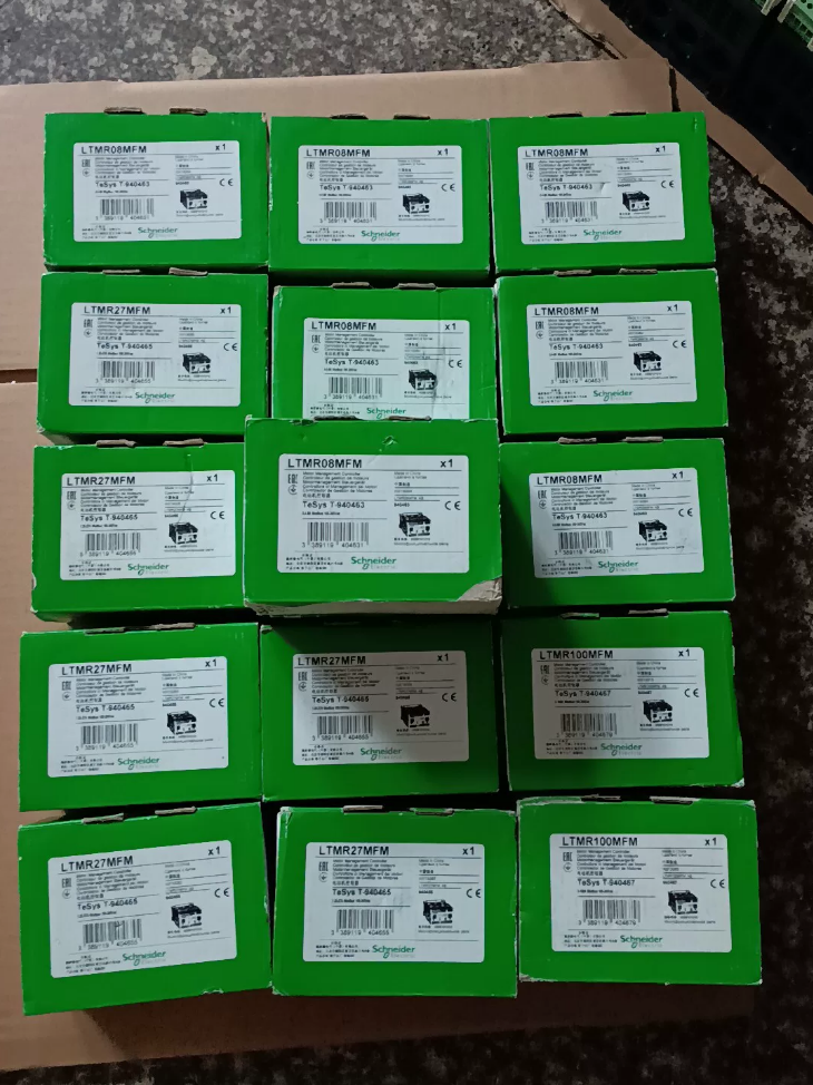

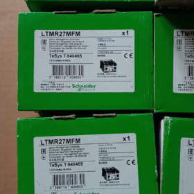
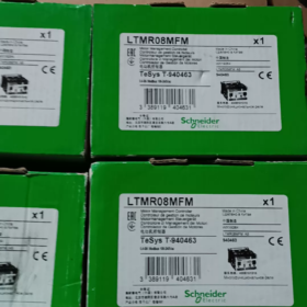
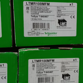
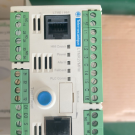
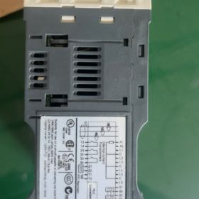
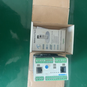
Anwendungsgebiete von Schneider LTMR27MFM (TeSys T)
Aktuelle Bewertung: 1.35~27A intelligenter Management-Controller für 3-Phasen-Asynchronmotoren, Ausgestattet mit Modbus-RTU-Kommunikation. Weit verbreitet in MCC-Schränken für integrierten Motorschutz eingesetzt, Stromüberwachung und Datenfernübertragung.
Aufschlüsselung des Modellcodes
LTMR27MFM
LTMR: TeSys T Motormanagement-Controller Basiseinheit
27: Strommessbereich 1,35–27 A (Integrierte Stromwandler)
M: Kommunikationsschnittstelle → Modbus RS485
FM: Steuerversorgung 100–240 VAC (Wechselstrom)
Querverweis innerhalb der Serie: LTMR27EFM = Ethernet; LTMR27CFM = CANopen
- Wichtigste elektrische Spezifikationen
| Artikel | Parameter |
| Motorstrombereich | 1.35 … 27 A (eingebauter CT, kein externer Stromwandler erforderlich) |
| Stromversorgung des Controllers | 100~240 V Wechselstrom 50/60 Hz (große Toleranz: 93.5~264 V) |
| Kommunikation | Modbus RTU RS485, Klemmenblock + RJ45-Dual-Port; Adresse 1~247; Baudrate 1,2k~19,2k |
| Digitale I/O | 6 digitale Eingänge; 3 KEINE Relaisausgänge + 1 Fehlerrelais (1NO+1NC) |
| Belastbarkeit des Relaiskontakts | 5A /250VAC; 5A /30VDC |
| Montage | DIN-Schienenmontage |
| Gesamtabmessungen | B91 mm × H61 mm × T122,5 mm; Nettogewicht 0.53 kg |
| Betriebstemperatur | -20 ℃ ~ +60 ℃; Lagertemperatur -40~80 ℃ |
| Schutzklasse | IP20 (für den Schrankinneneinbau) |
- Integrierte Schutzfunktionen
✅ Thermischer Überlastschutz (thermisches Modell)
✅ Phasenverlust & 3-Phasenstromunsymmetrieschutz
✅ Blockierter Rotorschutz, Langanlaufschutz
✅ Unterlastschutz (Trockenlauf-/Riemenbruchüberwachung)
✅ Erdschlussschutz (interne oder externe Nullsystem-CT)
✅ Unterstützung für PTC-Motor-Thermistor-Eingang
✅ Fehlerprotokollierung, Reisegeschichte, Betriebsstundenzähler
- Messfähigkeit (Stromspannung & Leistungsmessung mit LTME-Erweiterungsmodul)
Messung der Basiseinheit: 3-Phasenstrom, durchschnittlicher Strom, Unsymmetriestrom, Erdschlussstrom;
Bei Ausstattung mit LTME-Erweiterungsmodul: zusätzliche 3-Phasen-Spannung, Wirk-/Blindleistung, Leistungsfaktor, Energiemessung.
- Inbetriebnahmesoftware
Konfiguration über die SoMove-Software (TeSys T DTM). Schließen Sie den PC zur Parametereinstellung direkt über den vorderen RJ45-HMI-Anschluss an, Fehlerauslesung und Echtzeitüberwachung.
Optionales lokales Anzeigefeld: LTMCU / LTMCUF.
- Hinweis zum Lebenszyklus
Die vollständige LTMR TeSys T-Serie wird derzeit eingestellt (EOL).
Offizieller Bestellschlusstermin: 30 Sept 2026; Der technische Support endet: 31 Jan 2027
Ersatz der neuen Generation: TeSys Tera
Haupteinheit: LTMTMFM (Modbus, 100~240VAC/DC)
Aktuellen Sensor anpassen:
2.5~25A → LTMTCTV25UT (Beste Übereinstimmung mit der ursprünglichen 1,35-27-A-Anwendung)
⚠️ Verkabelungslayout und Modbus-Registerzuordnung sind zwischen alten und neuen Serien nicht vollständig kompatibel. Eine Nachrüstung vor Ort erfordert eine Neuinbetriebnahme des Programms.
- Typische Anwendung
MCC Motor Control Center, Wasserpumpen, Fans, Kompressoren, Förderer; Projekte in der Wasseraufbereitung, HVAC, Metallurgie und Zementindustrie.
- Schnelle Unterscheidung ähnlicher Modelle
LTMR27MFM:1.35~27A, Modbus, 100~240VAC
LTMR100MFM:5~100A, Modbus, 100~240VAC
LTMR27EFM:1.35~27A, Ethernet/IP
Hauptindustriesegmente
- Kommunale Wasserversorgung & Abwasserbehandlung (Häufigste Anwendung)
✅ Kommunale Abwasseranlagen, Wasserwerk, Pumpstationen
✅ Typische Belastungen: Tauchpumpen, Kreiselpumpen, Schlammrückführpumpen, Belüftungsgebläse, Schaber
Wesentliche Anforderungen erfüllt: Unterlastschutz (Trockenlaufschutz), Erdschlussschutz, Fernalarmierung bei Fehlern, Energieüberwachung.
- HVAC, Gewerbebauten & Aufbau elektromechanischer Systeme
✅ Einkaufszentren, Krankenhäuser, Rechenzentren, Kühlanlagen für Industrieparks
✅ Typische Belastungen: Kaltwasserpumpen, Kühlwasserpumpen, Kühlturmventilatoren, Abluftventilatoren, AHU-Fans
Vorteil: thermische Überlastung & Schutz vor blockiertem Rotor; Modbus-Anbindung an die Gebäude-GA-Anlage für aktuelle Daten und Störungsmeldungen.
- Zement, Baustoffe & Produktionslinien für den Zuschlagstoffabbau
✅ Bandförderer, Becherwerke, Hilfsantriebe für Rollenpressen, Staubabsaugventilatoren, Silo-Entleerungsausrüstung
✅ Gezielter Schutz: Schutz vor blockiertem Rotor, Langanlaufschutz, Phasenunsymmetrieschutz, um ein Durchbrennen des Motors durch mechanische Blockierung zu vermeiden.
- Chemisch & Pharmazeutische Industrie
✅ Umwälzpumpen, Rührwerksmotoren, Motoren für Hilfsluftkompressoren, Staubventilatoren
✅ Unterstützt den PTC-Thermistoranschluss zur Überwachung der Motorwicklungstemperatur; schnelle Auslösung bei Phasenausfall und Erdschlüssen zur Einhaltung industrieller Sicherheitsstandards.
- Essen & Getränk, Verpackungsproduktionslinien
✅ Fördermotoren, Gebläse, Waschpumpen, Antriebe für Verpackungsmaschinen
Präzise Unterlastüberwachung zur Erkennung von Materialmangel oder Bandablösung; Die Fehlerhistorie erleichtert die Wartung der Produktion.
- Schienenverkehr & Elektromechanische Tunnelsysteme
✅ Tunnelstrahlventilatoren, Entwässerungspumpen, Rauchabzugsventilatoren
Zuverlässiger Schutz für Feuerwehrmotoren; Daten-Upload in das Tunnel-SPS-Steuerungssystem.
- Kraftwerkszusatzausrüstung
✅ Umwälzpumpen für Wasser, Lüftungsventilatoren, Förderbänder zur Aschehandhabung; Standardkomponente in den MCC-Räumen des Kraftwerks.
- Hafen & Logistiklager
✅ Förderer, Hilfsantriebe für Stapler, Staubabsaugventilatoren, Ölpumpen für hydraulische Stationen
Passende Motorleistungsreferenz (380V-3-Phasen-Motoren)
LTMR27MFM Messbereich 1,35–27 A
Geeigneter Motorleistungsbereich: 0.75kW~13kW Dreiphasen-Asynchronmotor.
Nicht empfohlene Anwendungsszenarien
- Motoren über 13 kW (Wählen Sie stattdessen die LTMR100-Serie)
- Geräte mit häufigem Vorwärts-/Rückwärtsdrehen und starkem Impulsrüttelbetrieb (Die Parameter des thermischen Modells erfordern eine besondere Bewertung)
- Explosionsgeschützte Gehäuse ohne ausreichende Wärmeableitung (Die Umgebungstemperatur muss ≤60℃ bleiben)
Auswahlvorteile abgestimmt auf die Betriebsbedingungen
Integrierte Stromwandler, kein externes CT erforderlich, vereinfacht die Schrankverkabelung;
Modbus RS485-Schnittstelle, Nahtlose Verbindung mit Schneider PLC (Modicon M241/M251/M340 usw.);
Umfassendes Schutzpaket: Überlast, blockierter Rotor, Phasenverlust, aktuelle Unsymmetrie, Unterlast, Erdschluss, PTC-Temperaturüberwachung;
Aufzeichnung der Fehlerhistorie & Betriebsstundenstatistik, konform mit Smart Factory- und Energiemanagementprojekten.
Funktionsprinzip des Rotorblockierschutzes beim Schneider TeSys T LTMR27MFM
Der LTMR27MFM implementiert einen Rotorblockierungsschutz durch Echtzeit-3-Phasen-Stromabtastung + Beurteilung der Zeitschwelle, in zwei unabhängig konfigurierbare Modi aufgeteilt: Schutz vor blockiertem Rotor beim Start und Schutz vor blockiertem Rotor im laufenden Zustand.
- Hardware-Stiftung
Der LTMR27MFM verfügt über integrierte 3-Phasen-Stromwandler, um den Statorstrom kontinuierlich mit hoher Geschwindigkeit abzutasten. Die interne MCU rechnet in Echtzeit:
- Effektivwert von Drehstromströmen
- Verhältnis zwischen Momentanstrom und Nennbetriebsstrom
- Dauer des Überschreitungszustands
Keine zusätzlichen externen Sensoren erforderlich; Die Diagnose beruht ausschließlich auf der aktuellen Signaturanalyse.
- Zwei Schutzmodi bei blockiertem Rotor (Unabhängig in SoMove konfiguriert)
Modus 1: Schutz vor blockiertem Rotor beim Motorstart
Anwendungsszenario: Motor kann aufgrund mechanischer Blockierung beim Start nicht beschleunigen
- Urteilsfenster: Der Controller identifiziert die Startreihenfolge (Stromstoß, Motor im Stillstand vor Beschleunigung)
- Logik:
Wenn Anlaufstrom > Startschwelle bei blockiertem Rotor, und Dauer ≥ Startverzögerung bei blockiertem Rotor → Auslösebefehl ausgelöst
- Einstellbare Parameter (SoMove):
Anlaufstrom bei blockiertem Rotor: typischer Bereich 1,5–8× Motornennstrom Ie (Standard 5Dh)
Startverzögerung bei blockiertem Rotor: typischer Bereich 0,5–10 s
Zweck: Verhindern Sie ein Durchbrennen der Wicklung, das durch anhaltend hohen Strom verursacht wird, wenn der Motor beim Starten blockiert wird; Unterscheiden Sie zwischen permanentem Blockieren und normalem, kurzzeitigem Anlaufstrom.
Modus 2: Schutz vor blockiertem Rotor während des stationären Betriebs
Anwendungsszenario: Eine mechanische Blockierung tritt auf, nachdem der Motor die Nenndrehzahl erreicht hat (Riemenklemmung, Pumpenlaufrad klemmt, Einklemmen von Fremdkörpern)
- Urteilsfenster: Die Steuerung bestätigt, dass der Motor die Beschleunigung abgeschlossen hat und in einen stabilen Betrieb übergeht
- Logik:
Wenn Betriebsstrom > Schwellenwert für gesperrten Rotor, und Dauer ≥ Running Blocked Rotor Delay → Auslösebefehl ausgelöst
- Parametereigenschaften:
Der Schwellenwert für den Betrieb eines blockierten Rotors ist im Allgemeinen niedriger eingestellt als der Startschwellenwert (typischerweise 1,8~4 Dh), mit kürzerer Verzögerung für eine schnelle Fehlerisolierung.
- Vollständiger interner Entscheidungsworkflow
- LTMR tastet kontinuierlich dreiphasige Ströme ab und überwacht aktuelle Schwankungstrends;
- Unterscheidet automatisch drei Betriebszustände: Stillstand → Anlauf → Dauerlauf;
- Aktiviert die entsprechenden Schwellenwertregeln für blockierte Rotoren je nach Betriebszustand;
- Startet die Zeitmessung, sobald der Strom kontinuierlich den eingestellten Schwellenwert überschreitet;
- Wenn das Timing die konfigurierte Verzögerung erreicht:
✅ Interne Schutzsequenz aktiviert;
✅ Fehlerrelaiskontakt ändert seinen Zustand;
✅ Trennt den Steuerkreis des Schützes;
✅ Speichert den Fehlercode BLR (Blockierter Rotor) vor Ort;
✅ Lädt Informationen zu Fehlern bei blockiertem Rotor über Modbus an die übergeordnete SPS hoch.
⚠️ Kritische Auszeichnung: Schutz vor blockiertem Rotor ≠ Schutz vor thermischer Überlastung
Thermischer Überlastschutz: Basierend auf dem thermischen Akkumulationsmodell des Motors, Fahrten bei anhaltender leichter Überlastung; langsame Reaktionscharakteristik.
Schutz vor blockiertem Rotor: Schnell wirkender, unabhängig wirkender Schutz gegen schweren plötzlichen Überstrom, der durch mechanische Blockierung verursacht wird, Kompensation der langsamen Reaktion des Wärmeschutzes.
- Wichtige Inbetriebnahmerichtlinien
- Der Motornennstrom Ie muss genau eingegeben werden
Alle Schwellenwerte für blockierte Rotoren werden als Vielfache von Ie berechnet. Eine falsche Einstellung führt zum Versagen des Schutzes.
- Tuning-Prinzipien für Verzögerungen
Fans & Kreiselpumpen: Längere natürliche Startzeit → Verlängerung der Startverzögerung bei blockiertem Rotor, um Fehlauslösungen zu vermeiden.
Förderer & Brecher: Hohes Risiko einer mechanischen Blockierung → Minimieren Sie die Verzögerung beim Blockieren des Rotors, um einen schnellen Schutz zu gewährleisten.
- Schutzkoordination
Der Schutz vor blockiertem Rotor kann zusammen mit einem Phasenausfall aktiviert werden, Ungleichgewicht, Unterlast- und PTC-Temperaturschutz für mehrschichtige Sicherheit.
- Häufige Fallstricke bei Einstellungen
Stellen Sie den Schwellenwert für den blockierten Rotor nicht höher ein als den tatsächlichen Anlaufstrom des Motors; Andernfalls reagiert der Schutz während des blockierten Startvorgangs nicht.
- Fehlererkennung nach der Auslösung
Mit lokalem Anzeigepanel LTMCU: Fehlercode BLR wird auf dem Bildschirm angezeigt
SoMove-Fehlerprotokoll: Als blockierter Rotor aufgezeichnet
Entsprechendes dediziertes Modbus-Fehlerregisterbit für HMI/PLC-Alarme.
- Funktionelle Einschränkungen
Der Schutz bei blockiertem Rotor beruht ausschließlich auf der Stromsignatur des Stators. Seltene Randfallbeschränkung:
Wenn bei geringer Last eine mechanische Blockierung auftritt und der Strom nicht über den Schwellenwert steigt, Stall kann nicht erkannt werden. Für solche Bedingungen, implementieren Sie eine redundante Überwachung über Unterlastschutz oder Vibrationssensoren.





NH42-63-318x560.png "Automatische Transferschalter vom Typ CHINT PC (ATS)NH42-63/4SZ")



