 Schütz,Leistungsschalter,Sensor,Encoder,SPS,Konverter

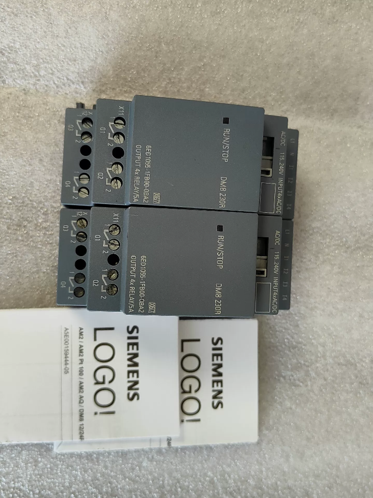

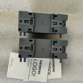
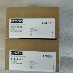
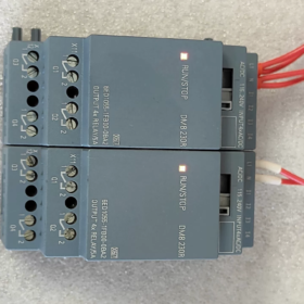
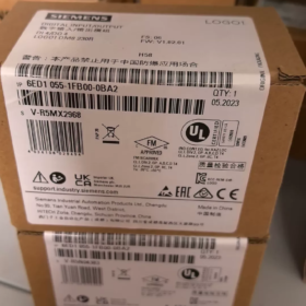
Vollständiger Name: LOGO! DM8 230R Digital-E/A Erweiterungsmodul (LOGO! 8 Serie)
- Interpretation des Modellcodes
6ED1055-1FB00-0BA2
6ED1055: Präfix für LOGO! 8 Serienerweiterungsmodule
1FB: DM8 230R, 115/230 V AC/DC-Stromversorgung, 4DI/4DO-Relaisausgang
00: Hardwareversion
0BA2: Firmware-Version (LOGO!8 Plattform, Inkompatibel mit LOGO!6/7 (0BA6/0BA7) Haupteinheiten)
- Grundlegende elektrische Spezifikationen
| Artikel | Spezifikation |
| Stromversorgung | 115~230 V AC/DC (85~265 V Wechselstrom; 100~253 V Gleichstrom) |
| DI-Digitaleingang | 4 Kanäle, universelles AC/DC-Signal |
| Logik 0: <40 V AC/<30 V DC | |
| Logik 1: >79 V AC / >79 V DC | |
| Eingabeverzögerung: 0→1=40 ms; 1→0=75 ms | |
| Digitaler Ausgang DO | 4 Kanäle schalten normalerweise offene, isolierte Kontakte frei |
| Widerstandslast: 5 A / 250 V und | |
| Induktive Last: 3 A / 250 V und | |
| Mindestlaststrom: 100 mA | |
| Maximale Schaltfrequenz: 2 Hz (widerständig); 0.5 Hz (induktiv) | |
| Montage | 35 mm DIN-Schiene, Breite 2 DER (35.5 mm) |
| Gesamtabmessungen | B35,5 × H90 × T58 mm |
| Schutzklasse | IP20 (Nur für den Schrankeinbau) |
| Betriebsumgebungstemperatur | -20 ℃ ~ +55 ℃, keine kondensation |
| Gewicht | Ca. 0.17 kg |
- Kompatibilitätsanweisungen
✅ Unterstützte Haupteinheiten: LOGO! 8 / 8.2 / 8.3 (0BA8 und neuere Firmware)
Typische Hauptgerätemodelle: 6ED1052-1FB08-0BA0, 6ED1052-1FB08-0BA1 und andere 230 V Haupteinheiten
❌ Nicht unterstützt: LOGO! 6, LOGO!7 (0BA6/0BA7) Haupteinheiten. Das Protokoll des Rückwandbusses ist unterschiedlich, Kommunikation nicht verfügbar
- Terminaldefinition (Spitze: Leistung & Eingang; Unten: Ausgabe)
Obere Terminals (Stromversorgung + Eingang)
L1, N: Modul-Betriebsstromversorgung
I1, I2, I3, I4: 4 digitale Eingänge
Untere Terminals (Relaisausgang)
Q1, Q2, Q3, Q4: 4 Unabhängige Relais-Schließer-Kontaktgruppen (2 Anschlüsse pro Kanal, kein gemeinsames Terminal)
⚠️ Wichtig: Vier Relais sind galvanisch getrennt; An jeden Kanal können unabhängig voneinander unterschiedliche Spannungskreise angeschlossen werden
- Typische Anwendungsszenarien
Kleine HVAC-Steuerung, Wasserpumpe & Lüftersteuerung, Beleuchtungskreise, Türverriegelung, einfache Förderstrecken. Ideal für Standorte, die mit vorhandenen ausgestattet sind 220 V AC-Sensoren und Schützschaltungen ohne zusätzliche DC-Stromversorgung.
- Auswahlrichtlinien & Häufige Fallstricke
- Das Eingangssignal muss größer sein 79 V zuverlässig als Logik erkannt werden 1; Niederspannungssignale können nicht verwendet werden.
- Mechanische Kontakte des Relais nicht für Hochfrequenzschaltung geeignet. Wählen Sie Transistor-Ausgangsmodule für häufigen Betrieb.
- Maximale Erweiterungsgrenze: Ein einziges LOGO! Haupteinheit kann bis zu angeschlossen werden 4 Erweiterungsmodule.
- All input channels are recommended to use the same phase power. Do not connect I1~I4 across different phases to avoid false triggering caused by induced voltage.
- Install RC snubbers or freewheeling diodes in parallel with inductive loads (Schütze, Magnetventile) to extend relay service life.
- Vergleich mit ähnlichen Serienmodellen
6ED1055-1FB10-0BA2 (DM16 230R): 8DI+8DO relay version with doubled I/O capacity
6ED1055-1HB00-0BA2 (DM8 24R): 24 V DC powered version
Complete Technical Documentation for Siemens 6ED1055-1FB00-0BA2 (LOGO! DM8 230R)
- Grundlegende Produktinformationen
Bestell-Nr.: 6ED1055-1FB00-0BA2
Produktname: LOGO! DM8 230R Digital Expansion Module (LOGO!8 Serie)
Funktion: 4AUS / 4DO relay output expansion module
Positionierung: Extend I/O capacity for LOGO!8/8.2/8.3 Haupteinheiten, kann nicht eigenständig ausgeführt werden
- Full Model Code Interpretation
6ED1055 1FB00 0BA2
- 6ED1055: LOGO! 8 series expansion module category
- 1FB: DM8 230R, 115~230 V AC/DC power supply, 4-channel AC input, 4 independent normally-open relay outputs
- 00: Hardware-Revision
- 0BA2: Firmware-Version (LOGO!8 Plattform, Inkompatibel mit LOGO!6/7 (0BA6/0BA7) Controller)
- Detailed Electrical Specifications
3.1 Stromversorgung
| Parameter | Spezifikation |
| Nennspannung | 115…230 V AC/DC |
| Betriebsbereich | Wechselstrom: 85~265 V; Gleichstrom: 100~253 V |
| Frequenzbereich | 47~63 Hz |
| Module Power Consumption | Max. 2.2 VA |
3.2 DI-Digitaleingang (I1, I2, I3, I4)
Menge: 4-Kanal universeller AC/DC-Eingang
Logik 0: <40 V Wechselstrom / <30V DC
Logik 1: >79 V AC / >79 V DC
Verzögerung der Eingabeantwort: 0→1: 40 MS; 1→0: 75 MS
Eingabetyp: Passiver Wechselspannungseingang, 24 V DC-Signale sind nicht zulässig
Maximale Kabellänge: 100 M (ungeschirmtes Kabel)
3.3 Relaisausgang DO (Q1~Q4, isolierte Schließerkontakte)
⚠️ Vier Relais sind gegenseitig isoliert; An jeden Kanal können unterschiedliche Spannungskreise angeschlossen werden
|Lasttyp|Kontaktbewertung|
| —| —|
|Widerstandslast (Widerstände, Beleuchtung)|5 A / 250 V und|
|Induktive Last (Schütze, Magnetventile)|3 A / 250 V und|
|Mindesttragstrom|100 mA (Unterhalb dieses Wertes kann es zu einer schlechten Kontaktleistung kommen)|
|Maximale Schaltfrequenz|Widerstandslast: 2 Hz; Induktive Last: 0.5 Hz; Mechanische Leerlaufbegrenzung:10 Hz|
|Verbotener Betrieb|Die Parallelschaltung mehrerer Ausgangskontakte zur Stromerhöhung ist verboten|
- Mechanisch & Umgebungsparameter
Montage: 35 mm Standard-DIN-Schiene
Breite: 2 DER (35.5 mm)
Gesamtabmessungen: B35,5 × H90 × T58 mm
Gewicht: Ca. 170 G
Schutzklasse: IP20 (Nur zur Verwendung als Innenschrank)
Betriebstemperatur: -20 ℃ ~ +55 ℃ (Kondensation verboten)
Lagerung & Transporttemperatur: -40 ℃ ~ +70 ℃
Relative Luftfeuchtigkeit: 5% ~ 95%, keine kondensation
Vibrationsfestigkeit: Entspricht IEC 60068-2-6
- Terminaldefinition
Obere Terminals (Stromversorgung + Eingang)
L1, N: Modul-Betriebsstromversorgung 115~230 V AC/DC
I1, I2, I3, I4: 4 digitale Eingänge
Untere Terminals (Relaisausgang)
Q1 zwei Anschlüsse: 1st Relais-Schließerkontakt
Q2 zwei Anschlüsse: 2und Relais-Schließerkontakt
Q3 zwei Terminals: 3Drittes Relais, normalerweise offener Kontakt
Q4 zwei Terminals: 4Schließerkontakt des Relais
- Systemkompatibilitätsregeln
✅ Unterstützte Haupteinheiten (LOGO!8 Plattform)
6ED1052-1FB08-0BA0, 6ED1052-1FB08-0BA1, alle LOGO!8.2 / 8.3 230 V-Controller
Maximale Expansionsmenge: Bis zu 4 Erweiterungsmodule pro LOGO! Haupteinheit
❌ Inkompatible Geräte
LOGO!6 (0BA6), LOGO!7 (0BA7) Legacy-Controller. Nicht übereinstimmendes Backplane-Kommunikationsprotokoll, kann nicht erkannt werden.
- Anforderungen an die Softwarekonfiguration
Programmiersoftware: LOGO! Soft Comfort V8.0 oder höher
- Wählen Sie im Projekt-Hardwarekatalog das entsprechende Erweiterungsmodulmodell aus;
- Die E/A-Adressen der Erweiterungsmodule folgen automatisch den Hauptgeräteadressen, keine manuelle Zuweisung erforderlich;
- Überprüfen Sie die Hardwareliste vor dem Herunterladen des Programms, um Fehler aufgrund von Versionskonflikten zu vermeiden.
- Zertifizierungen
CE, UL, CSA, CQC; Entspricht EN 61010-1, IN 55011 (EMV-Klasse B, Anwendbar für gewerbliche Gebäudeumgebungen)
- Technische Implementierungsrichtlinien (Offizielle Spezifikationen)
- RC-Snubber müssen parallel zu induktiven Lasten geschaltet werden (Magnetventile, Schützspulen) für Wechselstromkreise, um die Lebensdauer des Relais zu verlängern.
- Es wird empfohlen, alle Eingangskanäle mit derselben Phase zu versorgen. Schließen Sie die Eingangsklemmen nicht über verschiedene Phasen an, um Fehlauslösungen durch Streuspannung zu vermeiden.
- Mechanische Relaiskontakte haben eine begrenzte Lebensdauer. Wählen Sie Transistor-Ausgangsmodule aus (DM8 24T) für hochfrequente Start-Stopp-Anwendungen.
- Das Modul muss horizontal eingebaut werden; Eine vertikale umgekehrte Installation ist verboten.
- Halten Sie den Wärmeableitungsabstand in Schaltschränken ein, um einen Wärmestau zu vermeiden, wenn mehrere Module nebeneinander montiert werden.
- Vergleichstabelle ähnlicher Modelle
| Bestell-Nr. | Modell | Stromversorgung | E/A-Konfiguration | Ausgabetyp |
| 6ED1055-1FB00-0BA2 | DM8 230R | 115~230 V AC/DC | 4D/4C | Relais |
| 6ED1055-1FB10-0BA2 | DM16 230R | 115~230 V AC/DC | 8D/8C | Relais |
| 6ED1055-1HB00-0BA2 | DM8 24R | 24 In DC | 4D/4C | Relais |
Technische Anwendungsfälle für Siemens 6ED1055-1FB00-0BA2 (LOGO! DM8 230R)
Kernvorteile: Direkte Erfassung von 115~230 V AC/DC-Signalen; Isolierte Relaiskontakte treiben direkt an 220 V-Lasten ohne zusätzliche DC-Stromversorgung. Passend zum Logo! 230RCE-Haupteinheit (6ED1052-1FB08-0BAx). Geeignet für Neubau- und Sanierungsprojekte mit vollständig AC-Steuerkreisen vor Ort.
E/A-Zuordnung: 4AUS (220 V AC-Eingang) + 4 independent normally-open relay outputs
Fall 1: Doppelte Abwasserpumpe mit automatischer Wechselsteuerung für den Kellersumpf (Gebäudewasserversorgung & Drainage)
- Projektanforderungen
Zwei 220 V-Abwasserpumpen für Tiefgaragenschacht; Schwimmerschalter für hohen/niedrigen Füllstand mit 220 V-Kontaktsignale.
Hoher Wasserstand: Pumpen starten; Ultrahohes Niveau: Zwei Pumpen laufen gleichzeitig + hörbar & optischer Alarm;
Niedriger Wasserstand: Alle Pumpen stoppen;
Automatischer Zeitwechsel zwischen Haupt- und Reservepumpen für gleichmäßigen Verschleiß; Manuelle/automatische Umschaltung und Fehlerrückmeldungsfunktion.
- Hardwarekonfiguration
Haupteinheit: 6ED1052-1FB08-0BA1 (LOGO! 230RCE, Onboard 8DI/4DO)
Erweiterungsmodul: 6ED1055-1FB00-0BA2 ×1 (DM8 230R)
- E/A-Zuweisung
Onboard-Kanäle der Haupteinheit
I1: Automatischer/manueller Schalter; I2: Manuelle Startpumpe 1; I3: Manuelle Startpumpe 2; I4: Not-Aus;
Q1: Schütz der Pumpe 1; Q2: Schütz der Pumpe 2;
Erweiterungskanäle von DM8 230R
I5 (Modul I1): Schwimmerschalter für niedrigen Füllstand; I6 (Modul I2): Schwimmerschalter für hohen Füllstand; I7 (Modul I3): Ultra-High-Level-Schwimmerschalter; I8 (Modul I4): Ersatzteil;
F5 (Modul Q1): Alarmsummer für extrem hohen Füllstand; F6 (Modul Q2): Fehleranzeigeleuchte; F7, F8: Ersatzteil
- Lösungshighlights
Schwimmerschalter werden direkt an das Modul angeschlossen 220 V-Eingänge ohne Zwischenrelais. Vier isolierte Relaiskontakte können Alarme und Anzeigeleuchten separat mit unabhängigen Stromkreisen ansteuern. Keine zusätzliche DC24V-Stromversorgung im Schaltschrank erforderlich, Vereinfachung der Verkabelung.
Fall 2: Frische Luft & Abluftventilator-Verriegelungssteuerung für Bürogebäude (HVAC)
- Projektanforderungen
Vier 220 V Frischluft-/Abluftventilatoren mit planmäßigem Betrieb, Temperaturverknüpfung, Lüfterlauf-Feedback und Fehleralarm. Die integrierte E/A der Haupteinheit reicht nicht aus, um Zusatzmodul erweitert.
- Hardwareliste
LOGO! 230RCE-Haupteinheit + 6ED1055-1FB00-0BA2 ×1
- Modulnutzung
DI-Kanäle: 4-Rückmeldesignale für den Betrieb des Kanalschützes (220 V);
DO-Kanäle: Steuerschütze für zwei zusätzliche Abluftventilatoren, Fehler hörbar & optischer Alarm, Betriebskontrollleuchte des Systems.
- Technische Merkmale
Alle Steuersignale sind 220 V und; Isolierte Relaiskontakte ermöglichen die Einspeisung unterschiedlicher Phasen. Die kompakte 2TE-Breite spart Platz auf der DIN-Schiene für wandmontierte kleine Schaltschränke.
Fall 3: Zeitgesteuerte Gruppensteuerung der Pflanzenbeleuchtung (Gebäudebeleuchtungssystem)
- Anforderungen
Mehrere Gruppen von 220 V-Beleuchtungskreise für die Straßen- und Begrenzungsbeleuchtung von Anlagen; Zeitbasierte Stufenschaltung über interne Echtzeituhr; Lokale manuelle Überbrückung per Drucktaste; Rückmeldung des Fehlerstatus.
- Hardwarekonfiguration
LOGO! 230RCE (Integrierte Echtzeituhr) + DM8 230R (6ED1055-1FB00-0BA2)
- Modul-E/A-Zuordnung
AUS: 4-lokale manuelle Drucktasten des Kanals (220 V-Signal);
TUN: Antrieb AC-Schützspulen für 4 Beleuchtungsgruppen.
- Auswahlgrund
Modulrelais unterstützt maximal 5 Eine ohmsche Last, ist in der Lage, kleine Schütze direkt anzusteuern. Beleuchtungsstromkreise sind galvanisch getrennt; Der Ausfall eines einzelnen Stromkreises wirkt sich nicht auf andere aus.
Fall 4: Einfacher automatischer Transferschalter für die doppelte Stromversorgung einer kleinen Pumpstation
- Prozessanforderungen
Zwei 220 V-Steuerstromquellen (hauptsächlich + stehen zu). Automatisches Umschalten auf Standby-Stromversorgung bei Ausfall der Hauptstromversorgung; Sperre, um Parallelbetrieb zu verhindern; Statusanzeige und Fehleralarm verfügbar.
- Hardwarekonfiguration
LOGO! 230RC-Haupteinheit + 6ED1055-1FB00-0BA2
- E/A-Zuweisung
DI-Erweiterung: Rückmeldungssignale zur Erkennung der doppelten Versorgungsspannung;
Erweiterung DO: Steuern Sie die Einschaltspulen von zwei Leistungsschaltern und die Schaltabschlussanzeige.
Diese Konfiguration wird häufig bei Renovierungsprojekten für die Stromverteilung eingesetzt und von Siemens als offizielle typische Anwendung aufgeführt.
Fall 5: Verdunstungskühlventilator für Gewächshäuser & Verriegelungssteuerung des Sprühmagnetventils (Landwirtschaftliche Automatisierung)
Anforderungen
Kühlventilatoren und Sprühmagnetventile werden bei Temperatur automatisch aktiviert & Die Luftfeuchtigkeit überschreitet den Grenzwert; Abschaltung verzögern; lokale manuelle Tasten und Rückmeldung von Gerätefehlern.
Hardware
LOGO! 230RCE + DM8 230R
DI-Erweiterung: Manuelle Drucktasten, Thermorelais-Fehlerrückmeldung der Lüfter;
Erweiterung DO: 220 V-Spray-Magnetventil, Standby-Lüfterschütz.
Beachten
Magnetventile gehören zu den induktiven Lasten. Installieren Sie AC-RC-Dämpfer parallel zu den Relaisausgängen, um die Lebensdauer des Relais zu verlängern.
Fall 6: Sicherheitstor, Förderer- und Warnlicht-Verriegelung für leichte Fördergeräte (OEM-Maschinen)
Steuerlogik
Der Förderer darf nur starten, wenn das Schutztor geschlossen ist; Das Förderband stoppt sofort, sobald sich das Tor öffnet; Während des Betriebs bleibt die Warnleuchte eingeschaltet und der Summer ertönt intermittierend; Not-Aus hat höchste Priorität.
Hardwarekonfiguration
LOGO! Die E/A-Kapazität der Haupteinheit reicht nicht aus, erweitert über 6ED1055-1FB00-0BA2:
AUS: Endschalter für Sicherheitstür, Not-Aus, Reset-Taste;
TUN: Förderschütz, hörbar & optischer Alarm.
Allgemeine technische Pflichtspezifikationen für alle Fälle
- ✅ Eingangsverdrahtungsregel: Alle 4 DI-Kanäle müssen von derselben Phase L gespeist werden + N. Verdrahten Sie I1–I4 nicht über verschiedene stromführende Phasen hinweg, um Fehlauslösungen durch induzierte Spannung zu vermeiden.
- ✅ Relaisausgänge sind isolierte Schließerkontakte; An jeden Kanal können unterschiedliche Spannungskreise angeschlossen werden.
- ✅ Snubber-Komponenten sind für induktive Lasten zwingend erforderlich (Schütze, Magnetventile).
- ✅ Maximal 4 Erweiterungsmodule können mit einem LOGO kaskadiert werden! Haupteinheit.
- ✅ Nur kompatibel mit LOGO!8 / 8.2 / 8.3 Haupteinheiten (0BA8-Firmware). LOGO!7 und frühere Versionen werden nicht unterstützt.
- ✅ Kann nicht unabhängig betrieben werden; müssen auf der rechten Seite des Logos gestapelt werden! Hauptgerät über Erweiterungsbus.





NH42-63-318x560.png "Automatische Transferschalter vom Typ CHINT PC (ATS)NH42-63/4SZ")



