 Schütz,Leistungsschalter,Sensor,Encoder,SPS,Konverter

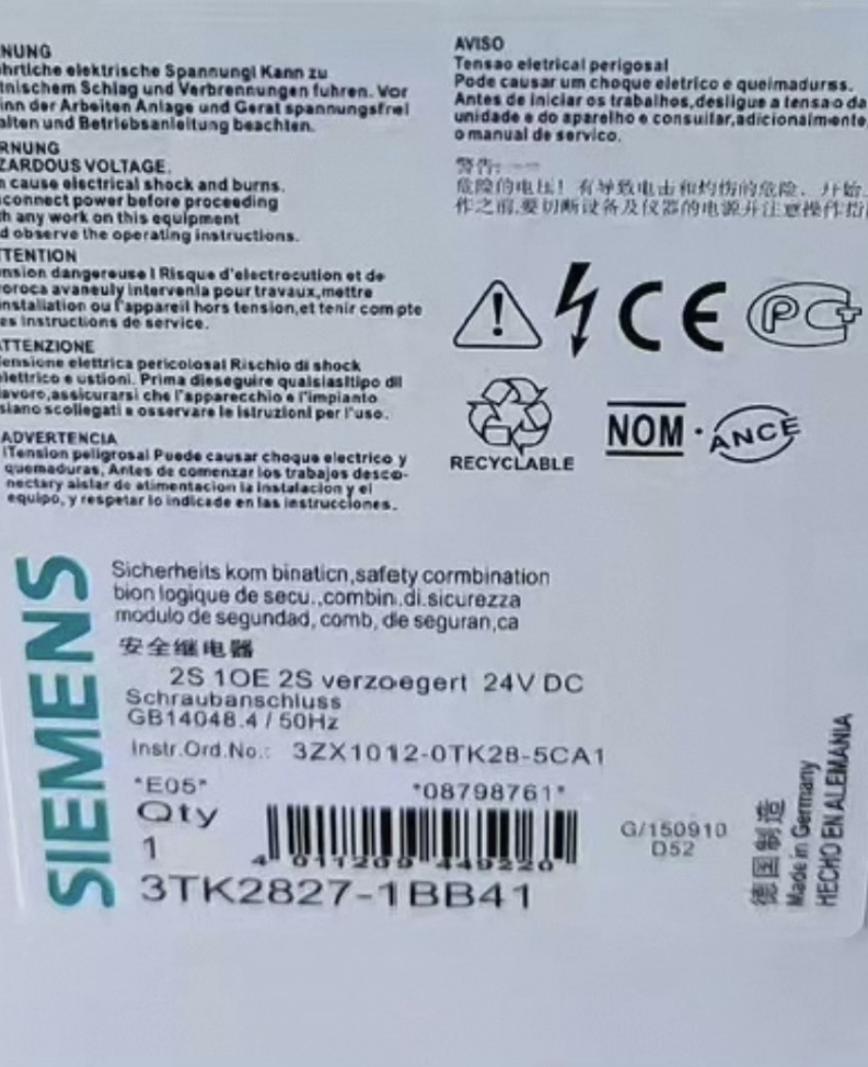

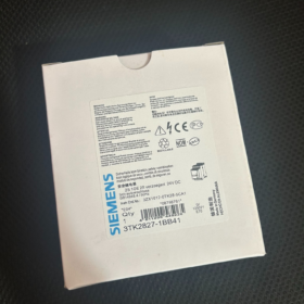
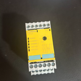
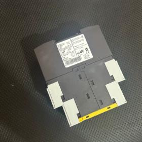
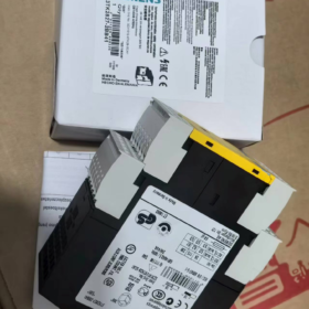
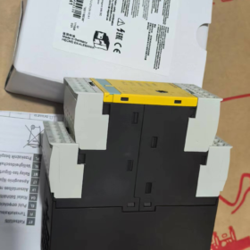
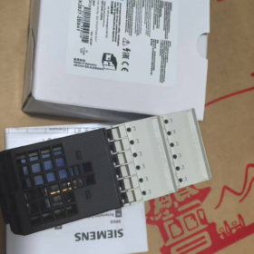
Status: Auslaufmodell (EOL). It belongs to the legacy 3TK28 series of basic safety units. 24 V DC-Versorgung, Schraubklemmen, monitored start, adjustable off-delay 0.05~3 s.
✅ Model Code Definition
3TK: SIRIUS Sicherheitsrelais Serie
28: Safety relay module
27: 2 instantaneous NO safety outputs + 2 delayed NO safety outputs, plus 1 NC signal feedback contact
1: Monitored start (external reset pushbutton mandatory)
BB: DC24V
4: Schraubklemmen
1: Delay version 0.05~3 s (Suffix 40 for same series = 0.5~30 s)
📋 Core Technical Specifications
| Artikel | Spezifikation |
| Liefern | DC24V (0.85~1.1Un) |
| Sicherheitsausgänge | 2KEIN sofortiger + 2NO off-delay |
| Signal Contact | 1NC for fault/status feedback |
| Verzögerungsbereich | 0.05 … 3 s adjustable via front potentiometer |
| Startmodus | Monitored start (controlled reset); auto-start not supported |
| Sicherheitsbewertung | SIL3 / PL e (EN ISO13849-1). EN954-1 Category4 for instantaneous circuit; Category3 for delayed circuit |
| Montage | DIN-Schiene, 45 mm Breite |
| Schutz | Housing IP40, terminals IP20 |
| Verdrahtung | Schraubklemmen, conductor 0.5~4 mm² |
| Anwendung | Nothalt, Schutztürüberwachung; Kategorie stoppen 0/1 (EN60204) |
| Erweiterbar | Compatible with external 3TK2830 contact expansion module to increase safety output capacity |
🛠️ Typical Application Scenarios
Dual-channel safety signal evaluation for emergency stop and safety guard doors, where delayed disconnection is required (inertial motor stop; delay before cutting off power circuit).
Dual-channel input with contact welding self-test and positively driven / force-guided contact structure, complying with machinery safety certification.
🔁 Replacement Selection (Discontinued Substitution)
The entire legacy 3TK28 series is superseded by the new generation 3SK1/3SK2 safety relays:
Recommended direct equivalent: 3SK1121-1CB42 (24VDC, monitored start, 2 instantaneous NO + 2 delayed NO, 0.05–3s delay)
⚠️ Warning: Terminal assignment and layout differ from 3TK2827-1BB41. Not a direct plug-and-play replacement. Rewiring and full safety loop reassessment are mandatory.
📌 Troubleshooting Checklist (Aus zweiter Hand / Installed Units)
- No output after power-up: Check reset circuit (Y33/Y34 monitored start terminals, external reset button required)
- Cannot reset: Verify consistency of dual-channel safety inputs; check for single-channel wire breakage
- Delay failure: Aged front potentiometer or damaged internal timing circuit
- Kontaktschweißen: Load exceeds AC15/DC13 rated capacity; front-end fuse protection required
- Second-hand inspection: Static continuity test on contacts; power-on test for dual-channel safety cut-off, timing function and reset logic
📎 Customs HS Code
85364900 (Electromagnetic safety relay, electrical switching apparatus)
⚠️ Wichtiger Hinweis
Only surplus stock or used spare parts are available. 3TK legacy series is not recommended for new projects; select 3SK1 directly. Nach dem Austausch, full validation of the machine safety circuit must be performed.
Siemens 3TK2827-1BB41 Safety Relay Overall Dimensions (DIN rail mounted unit)
Official datasheet dimensions: W × H × D = 44.8 mm × 138.5 mm × 120 mm
Engineering notation: 45mm(W) ×138.5mm(H) ×120mm(D). 45 mm is standard DIN rail module width.
Breite(W): 44.8 mm (nominal 45 mm on panel)
Höhe(H): 138.5 mm (including top and bottom terminals)
Tiefe(D): 120 mm (from DIN rail backplate to front face)
Montage: DIN rail snap-on mounting, oder Schraubbefestigung; any mounting orientation permitted
Nettogewicht: ca. 0.457 kg (same for all 3TK2827 variants)
📌 Cabinet layout note:
Reserve 45mm width occupancy on cabinet rail; depth ≥120 mm plus extra clearance for wiring.
The replacement model 3SK1121-1CB42 has a smaller footprint, so installation space must be rechecked for cabinet retrofits.
Working Principle of Siemens 3TK2827-1BB41 Safety Relay
Core definition: Dual-channel redundant, force-guided contacts, Ausschaltverzögerung, monitored start (controlled reset) safety evaluation module. Used for E-stop / safety gates to achieve EN60204 Stop Category 1 (controlled shutdown: brake first with delay, then cut main power).
- Internal Hardware Composition
- DC24V power supply unit (A1/A2)
- Two independent redundant safety input channels (Y11-Y12 / Y21-Y22): Dual-channel detection, connected to NC contacts of E-stop or safety door switches
- Two sets of independent internal force-guided relays, mutually cross-checked. A single fault will not result in loss of protection.
- Electronic timing circuit (front potentiometer adjustable 0.05~3s, Ausschaltverzögerung)
- Monitored start circuit Y33/Y34: Detects the falling edge of the reset pushbutton (triggered on button release), and detects short-circuit faults on reset wiring
- Ausgangskontakte
2NO instantaneous safety outputs (13-14, 23-24): Immediately open when safety signal trips; meets EN954-1 Category4
2NO delayed safety outputs (47-48, 57-58): Open after preset time once safety signal trips; Category3
1NC status feedback signal contact (31-32): Fehler / stop status signal for PLC diagnostics
Force-guided contact principle: NO and NC contacts are mechanically interlocked via rigid linkage. Even if NO contacts weld and stick closed, the mechanical linkage ensures the NC contacts cannot close, enabling detection of contact welding faults. This is the key difference between safety relays and standard relays.
- Complete Operating Logic (4 Stufen)
Stage 1: Power-up Standby
DC24V applied to A1/A2, POWER LED illuminates. Both safety input channels Y11-Y12 and Y21-Y22 must be fully closed (E-stop released, safety gate closed).
The module continuously compares the status of both channels. Mismatched channel states → fault detected, outputs locked off. Cross-wire short-circuit detection is also active.
Stage 2: Monitored Start (Key Feature)
Auto-start is NOT available!
With safety inputs fully closed, the external reset pushbutton (Y33/Y34) must be pressed and released. The module detects the falling edge pulse upon button release to enable internal relay energization.
Protection logic: If Y33/Y34 wiring is permanently shorted, the module identifies a fault and refuses startup to prevent unexpected machine auto-restart.
✅ After successful startup:
Instantaneous NO contacts (13-14, 23-24) schließen
Delayed NO contacts (47-48, 57-58) schließen
31-32 NC remains closed (normal running signal)
Stage3: Safety Trip (E-stop pressed / safety gate opened)
If either of dual safety input channels opens → module triggers hazardous state:
- Instantaneous outputs (13/14, 23/24) open immediately, cutting brake / Steuerkreise;
- Internal timer starts countdown (0.05~3s);
- When countdown completes, delayed outputs 47/48, 57/58 open to disconnect main contactors, allowing time for motor inertial stop and braking;
- 31-32 NC contact opens to output fault / stop signal externally.
Typical use case: High inertia motors; cut control circuit to initiate braking first, then main power after delay, complying with Stop Category1 controlled shutdown.
Stage4: Fehlerverriegelung, Manual Reset Mandatory
After E-stop reset / safety gate re-closed, outputs will NOT recover automatically.
Faults must be cleared, then reset pushbutton pressed again. The module runs self-test before reactivating outputs.
If internal faults including contact welding, channel mismatch or wiring short-circuit are detected, the module latches permanently. Power cycling cannot reset; hardware faults must be investigated.
- Sicherheitsmechanismus (Ausfallsicher)
- Dual-channel cross-check: Real-time comparison of two input channels; mismatch triggers immediate shutdown and latch
- Force-guided contact self-test: Contact adhesion checked on every operation
- Wiring short-circuit detection: Detects cross-short faults on safety and reset wiring
- De-energize-to-safe state: All safety outputs open upon loss of supply voltage
- Fehlerspeicherung: Hold shutdown state after fault, preventing automatic restart and secondary hazards
- Safety Rating Description
Instantaneous output circuit: IN 954-1 Kategorie 4, SIL3, PL e
Delayed output circuit: IN 954-1 Kategorie 3, SIL2, PL d
Grund: Timing electronics are single-channel, hence lower safety rating for delayed outputs.
- Häufige Missverständnisse
- Do NOT short to single-channel wiring; redundancy is lost and safety rating invalidated
- Monitored start ≠ auto-start; reset pushbutton must supply pulse signal. Permanent short of Y33/Y34 is forbidden
- Delay is OFF-Delay (de-energization delay), NOT power-on delay. Timer starts only after safety trip.
- Fault Determination Logic List (3TK2827-1BB41)
Once the module detects any of the following faults, safety outputs latch open. Most faults cannot be cleared by power cycling. Fault must be rectified before performing monitored reset.
- Safety Input Channel Faults (Y11-Y12 / Y21-Y22 dual channels)
- Single channel wire break: Mismatched channel states (one open, one closed) → immediate output cut-off and latch.
- Dual channels open simultaneously: Normal E-stop / safety gate trip, classified as normal shutdown, not hardware fault. After safety circuit recovery, reset required for restart.
- Cross short-circuit between dual channels (Y11 shorted to Y21, Y12 shorted to Y22): Module detects wiring short-circuit, rejects startup or trips and latches.
✅ Key rule: Safety loop must use two independent NC contacts; external parallel connection is not permitted.
- Reset Circuit Faults (Y33-Y34, monitored start terminals)
- Permanent short across Y33/Y34 (reset wiring shorted): Module identifies fault and blocks startup.
Prinzip: Monitored start relies on detecting falling edge of button release. Continuous short is treated as wiring fault to prevent power-on auto-start.
- Reset button stuck closed with no pulse: Even if safety loop is healthy, startup cannot be triggered after power-up.
- Reset circuit wire break: Reset pulse cannot be received; module fails to start.
III. Internal Relay Contact Faults (Force-guided contact self-check)
- Welded internal safety output contacts: Detected by self-test on each operation, outputs latched off.
Symptom: Safety input opens, but internal contacts remain welded. Module latches after fault detection; power cycle will not recover. Module replacement required.
- Mismatched status between the two internal redundant relays → fault latch.
- Supply Related Faults (A1/A2 DC24V)
- Supply voltage below 0.85Un (DC20.4V): Module unstable; safety outputs open (fail-safe characteristic).
- Voltage fluctuation or pulse interference: May trigger unintended shutdown; DC24V power buffer / fuse recommended.
- Delay Circuit Faults
- Damaged front potentiometer: Fixed delay value or zero delay. Usually will not trigger latch, but function lost, safety assessment invalid.
- Failed timing circuit: Delayed outputs fail to open upon safety trip; hazardous failure. Module must be replaced.
- Table to Distinguish Normal Shutdown vs Fault Trip
| Phänomen | Typ | Abhilfe |
| E-stop pressed / gate opened → outputs open; restore safety loop then reset to restart | Normal safety shutdown | Remove hazard, reset and restart |
| Power on, safety loop fully closed, reset button pressed with no response, cannot start | Fault latch | Check dual channels, reset wiring, cross shorts |
| Intermittent shutdown; reset allows short run before tripping again | Intermittent fault | Check loose wiring, aged contacts, Spannungsabfall der Versorgungsspannung |
| Fault latched; power cycle still cannot reset | Severe fault (contact welding / internal damage) | Replace safety relay immediately; do not continue operation |
⚠️ Safety Warning
In case of latched fault due to internal contact welding, bypassing the safety relay or shorting outputs to force startup is prohibited. This removes safety protection and violates EN ISO13849.





NH42-63-318x560.png "Automatische Transferschalter vom Typ CHINT PC (ATS)NH42-63/4SZ")



