 contactor,cortacircuitos,sensor,Codificador,SOCIEDAD ANÓNIMA,Convertidor

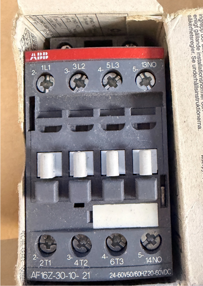

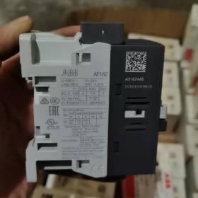
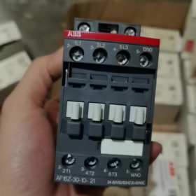
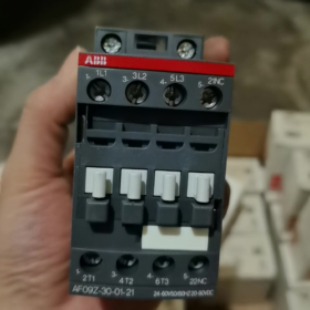
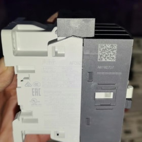
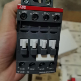
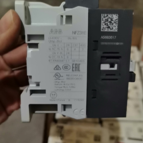
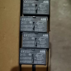
Original Factory Order No.: 1SBL176001R2110
- Definición de desglose del modelo
AF16Z 30 10 21
- AF16Z: serie AF; Z = Low-power electronic wide-range coil (direct PLC drive capable); Tamaño del marco 16 clase
- 30: Contactos principales: 3 Normalmente abierto (3NO), sin contactos principales normalmente cerrados
- 10: Contactos auxiliares incorporados: 1 Normalmente abierto (1NO), 0 Normalmente cerrado
- 21: Coil code → Control voltage: 24~60 V AC 50/60Hz / 20~60 V DC
⚠️ Difference between AF…Z and standard AF: Extremely low coil power consumption, supports direct driving by DC24V PLC outputs, resistant to voltage dips (compliant with SEMI F47).
- Core Electrical Ratings
Maximum main circuit voltage: 690 V y
AC-1 (carga resistiva), ≤40°C ambient: 30 A
AC-3 (3-motor de fase, 400 V): 18 A, adecuado para 7.5 kilovatios del motor
AC-3 (690 V): 10.5 A, máximo. 9 kilovatios
Montaje: Montaje en carril DIN, conexión de terminal de tornillo
Dimensiones generales: W. 45 mm × alto 86 mm × profundidad 77 milímetros
Temperatura de funcionamiento: -40~+70 °C (without thermal overload relay); -25~+60 °C (with thermal overload relay)
- Key Coil Characteristics
Wide-range AC/DC universal: AC 24~60 V / DC 20~60 V
Supresión de sobretensiones incorporada; no external RC snubber or diode required
Low holding power consumption, ideal for continuous energized operation
Resiste fluctuaciones y caídas de voltaje a corto plazo.
- Identificación de terminales
Circuito principal: 1L1-2T1, 3L2-4T2, 5L3-6T3
Contacto auxiliar: 14NO (Normalmente abierto)
- Alternativas comunes & Distinciones
- AF16Z-30-10-11: Mismo rango de voltaje, equipado con bobina AF estándar (bobina Z que no es de baja potencia); no puede ser controlado directamente por salidas PLC de baja corriente, no intercambiables.
- AX16-30-10: Serie económica AX, sin bobina electrónica de amplio rango, voltaje de control fijo; no puede reemplazar AF16Z.
- Para 1NO + 1Contactos auxiliares NC: Seleccionar modelo AF16Z-30-11-21.
- Aplicaciones típicas
Antes de los variadores de frecuencia, fans & bombas de agua, equipos de climatización, maquinaria semiconductora, Control de carga directa de salida CC PLC, Sitios industriales que requieren alta tolerancia a las fluctuaciones de voltaje..
TEJIDO AF16Z-30-10-21 contactor Documento Técnico de Instalación
Nro. de orden: 1SBL176001R2110
- Instrucciones generales de seguridad
⚠️ Toda la instalación, Los trabajos de cableado y mantenimiento deben realizarse con toda la energía desconectada.; El procedimiento de bloqueo y etiquetado es obligatorio.. El trabajo sólo debe ser realizado por electricistas calificados..
- Clase de protección: IP20. Solo para instalación en gabinete. No instalar al aire libre., ambientes húmedos, locations with heavy dust or corrosive gas exposure.
- Normas aplicables: CEI/EN 60947-1, CEI/EN 60947-4-1; UL/CSA certified.
- AF16Z is equipped with a low-power electronic wide-range coil with integrated surge suppression circuit. No external RC snubber or diode connection is required.
- Información básica del producto
2.1 Definición del modelo
AF16Z: serie AF, frame size 16, Z = low-power electronic coil
30: 3 contactos principales normalmente abiertos
10: Incorporado 1 contacto auxiliar normalmente abierto
21: Coil voltage range AC 24~60 V 50/60Hz / DC 20~60 V
2.2 Dimensiones generales
Ancho 45 mm × Height 86 mm × Depth 77 milímetros
2.3 Rating Summary Table
| Artículo | Parámetro |
| Carga resistiva AC-1 (40 째C) | 30 A |
| AC-3 motor load (400 V) | 18 A, compatible con 7.5 kW 3-phase motor |
| Tensión máxima de funcionamiento | 690 V y |
| Temperatura de funcionamiento (without thermal relay) | -40 째C ~ +70 째C |
| Temperatura de funcionamiento (with thermal overload relay) | -25 째C ~ +60 째C |
- Especificaciones de instalación mecánica
3.1 Métodos de montaje
Two mounting options available:
- Montaje en carril DIN (Recomendado)
Rail standard: TS35 (35×7.5 mm / 35×15 mm)
Operación: Hook the bottom latch onto the rail, press down until an audible click confirms locking. For removal, use a flat screwdriver to pry the bottom latch and lift upwards.
- Base Plate Screw Mounting
Fasten diagonally using 2 × tornillos M4; refer to outline drawing for mounting hole spacing.
3.2 Orientación de montaje & Autorización
- Montaje vertical (terminales superiores & abajo) privilegiado. 90° se permite el montaje lateral horizontal; Está prohibida la instalación al revés..
- Se pueden montar varias unidades una al lado de la otra sin reducir la corriente. Mantenga un espacio libre vertical de ≥15 mm para ventilación.; Mantener alejado de componentes que generen calor, como resistencias e inversores..
- Evite la instalación en lugares de alta vibración. Aceleración de vibración >0.5g requiere medidas de amortiguación de vibraciones.
- Especificaciones de cableado eléctrico
4.1 Definición de marcado de terminales
Circuito principal superior: L1, L2, L3 (Entrada de energía)
Circuito principal inferior: T1, T2, T3 (Salida de carga)
Las aplicaciones que no son UL permiten la alimentación desde arriba o desde abajo; Las instalaciones certificadas por UL requieren entrada de energía desde los terminales L superiores.
Terminales de bobina A1, A2: Entrada de señal de control (AC/DC no polarizado)
Contacto auxiliar 13-14: Contacto normalmente abierto incorporado (1NO)
4.2 Especificación del cable & Longitud de pelado
Longitud de pelado de cables estándar: 10 milímetros
Conductores del circuito principal: Cable de cobre sólido/trenzado 1~6 mm²; Casquillos recomendados para cables flexibles.
Control / conductores del circuito auxiliar: 0.75~2,5 mm²
4.3 Par de apriete (Obligatorio)
Terminales del circuito principal: 1.5 Nuevo Méjico
Bobina A1/A2 & terminales de contacto auxiliares: 1.2 Nuevo Méjico
Un par insuficiente provoca el sobrecalentamiento del terminal; Un par de torsión excesivo provoca que se rompa el hilo..
Herramientas recomendadas: Destornillador Pozidriv PZ2 / 5.5 destornillador dinamométrico plano mm.
- Notas críticas sobre la aplicación de bobinas (Característica principal de AF16Z)
- Rango de voltaje: CA24~60V / CC20 ~ 60 V, amplia compatibilidad de voltaje, accionamiento directo mediante salidas PLC DC.
- Consumo de energía de mantenimiento de bobina muy bajo, adecuado para funcionamiento energizado a largo plazo; cumple con los requisitos de inmunidad a caídas de voltaje SEMI F47.
- A1 y A2 no están polarizados; La polaridad no importa para el control DC24V..
- No aplique voltaje de control que exceda 60 V, de lo contrario, el módulo de la bobina electrónica será destruido.
- Instalación de accesorios opcionales
- Contactos auxiliares laterales (Serie CA4)
Ajuste a presión en las ranuras laterales izquierda/derecha sin herramientas. Máximo 2 Se pueden instalar juegos de contactos auxiliares laterales en AF16..
- Enclavamiento mecánico
Instalar para la configuración del circuito inverso de dos contactores AF16Z para evitar el cierre simultáneo y el cortocircuito entre las fases directa e inversa..
- Coincidencia de relé de sobrecarga térmica
Compatible con relés térmicos serie TA25DU, montaje directo a presión debajo del contactor.
- Procedimiento de puesta en servicio después del encendido
- En condiciones de apagado: Inspección visual para el cableado correcto., sin residuos metálicos, todos los terminales apretados al par especificado.
- Accione manualmente el mecanismo del contactor para confirmar un funcionamiento suave sin atascos..
- Pruebe el circuito de control de forma independiente: Aplique voltaje de control nominal a A1/A2; El contactor se activará de manera confiable y se desconectará suavemente al desconectarse la energía..
- Verificar la conmutación síncrona del contacto auxiliar 13-14 con funcionamiento por contactor.
- Conecte el circuito principal para realizar una prueba de funcionamiento sin carga.; Compruebe si hay ruidos anormales y aumento rápido de la temperatura del terminal..
- 30-prueba de funcionamiento con carga minuto; Vuelva a verificar la temperatura del terminal para garantizar que el aumento de temperatura se mantenga dentro de los límites permitidos..
- Fallos de instalación & Prácticas prohibidas
❌ Operaciones prohibidas:
Hilos sueltos expuestos en terminales de cable
Apretar terminales mientras está energizado
Tensión de control fuera del rango de 20~60 V
Bloqueo de canales de ventilación por encima y por debajo del contactor.
Instalación directa en ambientes con polvo combustible o condensación continua
Problemas comunes posteriores a la instalación
- Vibración del contactor/entrada inestable: Verifique que el voltaje de control esté por encima del nivel mínimo de operación; comprobar la caída de tensión en los cables de control.
- Sobrecalentamiento de terminales: Vuelva a apretar los terminales al par especificado; Confirme que la sección transversal del conductor sea adecuada..
- No detenerse cuando es impulsado por PLC: Confirmar que la unidad es AF16Z (bobina de baja potencia); La bobina AF16 estándar no puede ser accionada directamente por salidas de transistor PLC.
- Requisitos de mantenimiento
- Inspección periódica de temperatura terminal y ruido anormal..
- Evite conmutaciones repetidas por encima de la capacidad de corte nominal.
- Nunca opere el contactor sin el protector contra arco.. Reemplace la unidad completa cuando los contactos sufran una ablación severa..
Parámetros de vida mecánica de ABB AF16Z-30-10-21
El AF16Z comparte una construcción mecánica idéntica con el AF16 estándar.. Datos técnicos oficiales:
✅ Resistencia mecánica: 10 millones de ciclos de funcionamiento (10×10⁶ operaciones)
Condiciones de prueba: Tensión de control nominal, conmutación sin carga, temperatura ambiente estándar.
Parámetros clave de soporte
- Frecuencia máxima de funcionamiento mecánico: 3,600 operaciones por hora
El funcionamiento continuo de alta frecuencia no deberá exceder este límite para evitar el desgaste mecánico acelerado..
- Resistencia eléctrica de referencia (depende del tipo de carga, no es igual a la vida mecánica)
AC-3 (400 carga del motor V): Aprox.. 1,000,000 ciclos
AC-1 (carga resistiva): Aprox.. 1,600,000 ciclos
⚠️ La resistencia mecánica representa el límite de funcionamiento mecánico.; La vida útil en aplicaciones prácticas normalmente está determinada por la erosión eléctrica de los contactos..
Observaciones complementarias
- AF16Z solo se diferencia por su variante de bobina electrónica de amplio rango de bajo consumo. Armadura, La estructura mecánica de enlace y contacto es idéntica a la estándar AF16.; Las clasificaciones de resistencia mecánica permanecen sin cambios..
- La resistencia mecánica real disminuirá en entornos hostiles (polvo pesado, vibración continua, temperatura alta).
- Definición de resistencia mecánica: Ciclos de funcionamiento de activación/desconexión del contactor impulsados únicamente por bobina, sin carga conectada al circuito principal.










NH42-63-318x560.png "Interruptores de transferencia automática tipo PC CHINT (ATS)NH42-63/4SZ")



