 contactor,cortacircuitos,inversor solar,medidor electrico,baterias solares

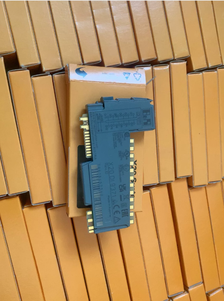

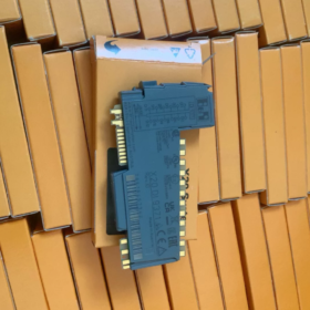
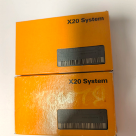
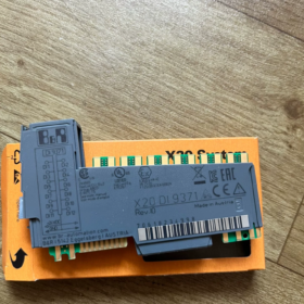
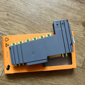
X20DI9371 Model Code Breakdown
X20: B&R X20-series I/O system (shared platform after IFM acquired B&R’s automation business)
DE: Entrada digital
9371: Module specification code
- Posicionamiento central
16-channel 24VDC digital input module compatible with sourcing/sinking types, designed for mounting on industrial standard X20 bus baseplates
Brand Lineup: IFM efector / B&R X20 I/O Series
- Key Electrical Technical Specifications
| Parámetro | Especificación |
| Number of Input Channels | 16 entradas digitales |
| Voltaje de entrada nominal | corriente continua 24 V (Rango de operación: 18–30 VCC) |
| Tipo de entrada | Universal NPN/PNP (compatible with sinking/sourcing sensors) |
| Input ON Threshold (High Level) | ≥11 VDC |
| Input OFF Threshold (Low Level) | ≤5 VDC |
| Typical Single-Channel Input Current | 2.5 mamá |
| Fixed Debounce Filter Time | 1 EM (extendable via software configuration) |
| Bus Interface | Internal high-speed X20 backplane bus |
| Fuente de alimentación | Module logic powered by backplane; field sensors powered by external 24V DC supply |
| Aislamiento eléctrico | Galvanic isolation per group of 8 canales |
| Clase de protección | IP20 (for cabinet installation only) |
| Rango de temperatura de funcionamiento | -20 ℃ to +60 ℃ |
| Método de montaje | DIN rail daisy-chain mounting on standard X20 baseplates |
III. Hardware Structure
- Channel Grouping: 16 digital inputs split into two isolated groups: CH0~CH7 and CH8~CH15
- Terminal Design: Spring-cage terminals for tool-free fast wiring
- Indicadores de estado: Individual green LED per channel (lit = active signal); dedicated RUN and ERR LEDs for bus fault diagnosis
- Dimensiones: Standard narrow X20 module with 12.5 mm de ancho
- Configuración de software & Compatibilidad
- Supported Controllers: IFM X20 / B&R X20 PLCs (X20CP, X20XC CPU series)
- Software de programación: All versions of Automation Studio (AS3.0 to AS4.9)
- Características funcionales
Channel short-circuit and wire break diagnostics (supports 2-wire sensors with line monitoring)
Event timestamping for high-speed signal capture
Configurable channel signal inversion logic
- Escenarios de aplicación típicos
- Digital signal acquisition for machine limit switches, photoelectric sensors and proximity switches
- Feedback signal collection for production line position sensors, safety gates and emergency stop circuits
- Centralized digital signal acquisition for packaging machinery, machine tools and material handling conveyors
- I/O expansion for complete IFM automated production lines
- Cross-Series & Referencia de reemplazo
Direct Drop-In Replacements (Fully Functionally Identical)
X20DI9371 (16-channel universal 24V digital input)
No revised suffix variants; identical model is fully interchangeable.
Distinction of Similar Models
- X20DI9372: 16-channel DI with enhanced diagnostic functions, pin-compatible hardware
- X20DI2371: 8-channel DI with half the channel count
- X20DO9321: 16-channel digital output module; cannot replace input modules
VII. Packing List
Standard Included Items
- X20DI9371 I/O module main unit ×1
- Pre-installed spring-cage terminal blocks
- Printed installation manual
Optional Separately Purchased Accessories
X20TB standard terminal baseplates (for daisy-chain expansion)
X20AC0100 bus termination cover
X20CA0100 expansion connecting cable
VIII. Common Fault Troubleshooting Matrix
| Síntoma de falla | Causa principal | Resolution Steps |
| Steady red ERR LED on module | Faulty backplane bus communication / poor baseplate contact | 1. Re-seat the module; 2. Verify termination covers at both ends of X20 bus; 3. Restart CPU |
| Channel LED remains off despite sensor output | 1. Cableado suelto; 2. Reversed input polarity; 3. Missing sensor power supply | Check 24V power supply, NPN/PNP wiring logic, and fasten spring terminals |
| Frequent false signal triggering | Insufficient debounce filter time, cable electromagnetic interference | Increase input filter duration to 5–10 ms in Automation Studio; apply shielding and grounding to signal cables |
| Complete signal loss for a full group of 8 canales | Broken isolated power supply for the group, disconnected common COM terminal wiring | Inspect 24V wiring for each group’s common COM terminal |
- Sourcing & Classification Supplementary Information
- Customs HS Code (Industrial Control I/O Module): 8537109000
- Certificaciones: CE, UL, GL marine classification certification; compliant for equipment export to Europe and North America


")

")
 Adoptando Flash industrial de 3,3 V con capacidad de 4 MB.. Está diseñado exclusivamente para S7-1200, PLC S7-1500, así como variadores y servoaccionamientos SINAMICS de la serie G/S/V.")
 y MHT2-50D (pinza de sujeción final)")

")
NH42-63-318x560.png "Interruptores de transferencia automática tipo PC CHINT (ATS)NH42-63/4SZ")


