 contactor,cortacircuitos,inversor solar,medidor electrico,baterias solares


Información básica
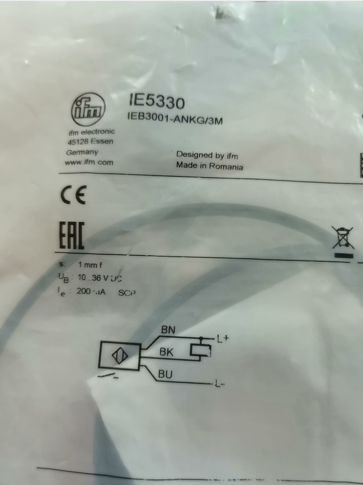
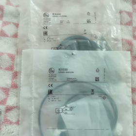
Full Model Code: IFM IEB3001-ANKG/3M (Commercial Model: IE5330)
Tipo de producto: M8 Shielded Inductive Sensor de proximidad (Flush Mountable)
End-of-Life Notice: Officially discontinued by manufacturer on Mar 31, 2026; replacement selection required.
Especificaciones principales
Thread Size: M8×1, Overall Length: 35 milímetros
Salida de cables: 3m PVC 3-core straight cable
Producción: NPN Normally Open (NO)
Distancia de detección: Estándar 1 milímetros (shielded flush type)
- Parámetros eléctricos básicos
Fuente de alimentación
Voltaje de funcionamiento: DC 10~36 V (compatible with standard 24V industrial control systems)
Quiescent Current: 15 mA @ 24 V
Protección incorporada: Protección contra polaridad inversa, protección contra cortocircuitos, protección contra sobrecarga
Características de salida
Tipo de salida: Colector abierto NPN (Sink Output)
Output Mode: Normalmente abierto (conducts when metal approaches)
Max Load Current: 200 mamá
Voltage Drop at Turn-On: ≤2.5 V
Frecuencia de conmutación: 750 Hz (suitable for high-speed counting)
Sensing Performance
Rated Sensing Distance Sr: 1 mm ±10%, Effective Operating Range: 0~0.8 mm
Metal Correction Factors:
Histéresis: 1%~15% of Sr (prevents signal chattering)
- Mecánico & Parámetros ambientales
- Material de la carcasa: Bronze-plated brass; sensing face: PBT plastic
- Clase de protección: IP67 (impermeable & a prueba de polvo, withstands short-time rinsing)
- Método de montaje: Flush shielded design (fully embeddable in metal brackets)
- Supplied Accessories: 2 pieces of M8 lock nuts as standard
- Temperatura de funcionamiento: -25 ℃ ~ +80 ℃
- EMC Compliance: Industrial standards EN55011 Class B, EN60947-5-2
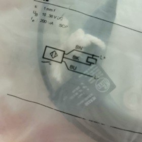
- 3-Wire Wiring Definition (3metros de cable)
| Wire Color | Función | Wiring Instruction |
| Marrón | DC+ 24V Positive | Connect to 24V terminal of PLC / fuente de alimentación |
| Azul | corriente continua- 0V Negative | Power common ground |
| Negro | NPN Signal Output | Connect load between 24V+ and black wire |
PLC Wiring Notes (NPN Sink Type)
Directly compatible with Japanese PLCs (mitsubishi / Omrón);
European standard PNP source-type PLCs require an intermediate relay for signal conversion.
- Escenarios de aplicación típicos
Position detection of small cylinders, positioning of miniature tooling fixtures
Counting metal workpieces on miniature conveying lines (750Hz high frequency)
Installation in compact equipment spaces (short slim M8 housing, L=35mm)
Metal detection for machine tools, automated assembly lines and 3C equipment
- Recommended Replacement Models After Discontinuation (Direct Drop-In Compatibility)
Identical Spec Drop-In Replacement (M8 shielded, 1milímetros, NPN NO, 3cable m)
- IE5331: New upgraded generation with fully identical parameters, abundant stock
- IEB3002-ANKG/3M (new series part number)
Alternate Output Versions
PNP Normally Open equivalent: IE5340
Unshielded M8 long sensing distance (2 milímetros): IE5090
- Common Troubleshooting Matrix
| Fenómeno de falla | Causa principal | Soluciones |
| No indicator light, complete failure to operate | Marrón & blue wires reversed; supply voltage below 10V | Verify wiring sequence, measure 24V power supply |
| No signal output when metal approaches | Detection gap over 0.8mm; excessive attenuation for aluminum/copper targets | Reduce mounting clearance; replace target with steel sensing plate |
| Frequent signal chattering | Loose mounting nuts; insufficient hysteresis; severe mechanical vibration | Tighten lock nuts, shorten detection distance |
| Output fails several seconds after power-on | Output short-circuit triggering built-in protection lockout | Disconnect load, power cycle to locate short circuit |
Key Distinction Points for Model Selection
- IE5330 Shielded Flush Type: 1mm distancia de detección, embeddable into metal holders, fuerte capacidad antiinterferencia;
- Unshielded M8 model IE5070: 2mm distancia de detección, non-embeddable, susceptible to interference from surrounding metal;
- Plug-in versions have no “/3METRO” suffix at model end; cable versions come with fixed 3-meter cable.
Complete Troubleshooting Guide for IFM IE5330 (M8 Shielded, NPN NO, 1milímetros)
Precondition Reference Parameters (Benchmark for Troubleshooting)
- Fuente de alimentación: DC 10~36 V, 3-wire system: Brown = 24V+, Blue = 0V, Black = NPN NO signal output
- Rated sensing distance Sr = 1mm (shielded flush design, effective working gap ≤0.8mm)
- Max load 200mA, built-in reverse polarity, short-circuit and overload protection
- Indicador: Yellow LED; lit when metal approaches, off without metal target
- IP67 protection class, operating temperature: -25 ℃ ~ +80 ℃
- Standard Layered Troubleshooting Procedure (Simple First, On-Site Priority)
Layer 1: Inspección visual & Montaje mecánico (5-Min Preliminary Check)
- Clean sensing face: Remove iron filings, cutting fluid, oil stains and dust; adhered metal debris causes continuous false triggering / permanent ON state
- Inspect housing & cable: Check for crushed insulation, broken conductors from bending, water ingress whitening, loose lock nuts
- Mounting Specifications (IE5330 is shielded flush type)
Fully embeddable inside metal brackets; side surrounding metal generates no interference
Detection gap must be ≤0.8mm; target surface perpendicular to sensing face
Minimum spacing ≥ 3×Sr = 3mm for multiple sensors mounted side-by-side to avoid mutual interference
- Metal Target Correction Factors (Primary cause of sensing distance attenuation)
Layer 2: Multimeter Test for Power Supply & Alambrado (High-Frequency Fault Source)
- Cut off power to verify wiring: Brown connected to 24V+, Blue to 0V, Black to PLC input (NPN sink)
- Power on and measure voltage across brown & blue terminals: Stable 10~36V required, onda <5%; sensor fails to start if voltage drops below 10V
- Reverse polarity lockout: Swapped brown/blue wires activate protection lockout, yellow LED stays off; power off for 3 minutes to reset and restore function
- Cable open circuit: Test continuity segmentally for brown, blue and black wires; cable inside cable chains for machine tools is most prone to breakage
- PLC Compatibility Note: IE5330 is NPN NO; PLC input common terminal must connect to 24V+. Direct connection to European PNP-type PLCs yields no signal; an intermediate relay is required for conversion.
Layer 3. Electrical Output Functional Test (Judge Sensor Integrity via Multimeter)
Standard voltage states of NPN NO IE5330 (measure black wire against blue wire 0V):
No metal target: Black wire ≈ DC24V (high level, yellow LED off)
Steel plate close to sensing face: Black wire ≈ 0~2.5V (low level, yellow LED ON)
Test Judgment Criteria:
- Normal voltage switching synchronized with yellow LED → Sensor intact; fault lies in downstream PLC / alambrado
- No voltage variation, LED unresponsive to metal movement → Sensor damaged or locked out by short-circuit protection
Layer 4. Interferencia electromagnética & Inspección Ambiental (Exclusive for Signal Chattering)
- Sensor cables routed parallel with inverter / servo power cables → High-frequency noise causes random signal fluctuation
- Long-distance unshielded cables with both ends of shield grounded (shield shall only be grounded at control cabinet single end)
- Magnetic interference generated by frequent switching of nearby welders, solenoid valves and contactors
- Ambient temperature exceeding 80 ℃ causes internal circuit drift and intermittent signal loss
- Fault Phenomenon Matrix (Fenómeno + Causa principal + One-Step Solutions)
Falla 1: Yellow LED never lights up after power-on, zero output
| Causa principal | Quick Check | Remedial Action |
| Reversed power polarity (marrón & blue swapped) | Multimeter detects reversed voltage polarity between brown & azul | Swap brown and blue power wires; power off and rest 3 mins for reset |
| Tensión de alimentación <10V or missing 24V rail | Voltage between brown & azul <10V / 0V | Replace regulated 24V DC power supply; upgrade wire gauge to reduce voltage drop |
| Internal breakage of brown / blue wires in cable | Segmental continuity test | Cut damaged section and re-crimp terminals, or replace entire 3m cable |
| Internal sensor burnout from overvoltage | Voltage previously exceeded 36V, lightning surge | Directly replace IE5330 or substitute model IE5331 |
| Tripped fuse on upstream circuit | Cortocircuito / overload protection triggered | Locate downstream short circuit, replace fuse then restore power |
Falla 2: Yellow LED permanently ON with no metal target nearby
- Iron filings / metal powder adhered to sensing face
Solución: Wipe sensing face with alcohol; install dust shield baffle
- Over-tight detection gap, metal base tightly attached to sensor head
Solución: Raise sensor with gaskets; control clearance at 0.4~0.8mm
- Short circuit between black output wire and 24V positive
Solución: Cut power, separate damaged cable insulation and isolate short points
- Internal breakdown of output transistor
Solución: Test with identical spare sensor; replace if faulty
Falla 3: Yellow LED lights when metal approaches, yet no PLC input signal
- PLC input common terminal connected to 0V (PNP configuration incompatible with NPN sensor)
Solución: Reconnect PLC COM terminal to 24V+
- Open circuit on black output wire; loose / oxidized terminals
Solución: Fasten terminals tightly, test black wire continuity and repair breaks
- Load current exceeds 200mA (direct drive of large solenoid valves)
Solución: Switch via intermediate relay; prohibit direct connection of high-power loads
- Burned PLC input channel
Solución: Move black wire to spare healthy input channel for verification
Falla 4: Chattering, intermittent signal, frequent false triggering / missed detection
- Detection gap near critical threshold of 0.8~1mm
Solución: Shorten clearance below 0.5mm for sufficient trigger margin
- Severe machine vibration loosens sensor nuts and shifts position
Solución: Double lock nuts with anti-loose washers
- Interference from power cables laid parallel with sensor wiring
Solución: Separate cable trays, cross wires perpendicularly; ground cable shield only at control cabinet end
- Target made of aluminum / stainless steel with heavy sensing distance attenuation
Solución: Fit steel sensing gaskets, reduce detection gap
- Ondulación excesiva de la fuente de alimentación, poor filtering of switching power supply
Solución: Connect 1000μF/35V electrolytic capacitor in parallel to power output terminal
Falla 5: Yellow LED extinguishes several seconds after power-on, output disabled (intermittent protection lockout)
- Output wiring shorted to ground (black wire touching 0V)
Solución: Disconnect black wire of sensor and power on alone; LED recovery indicates downstream short circuit, inspect wiring segmentally
- Load short-circuit / instantaneous overload triggers built-in short-circuit protection
Solución: Remove downstream load, test sensor under no-load condition
- Cable insulation damaged, persistent micro-short between black and blue wires
Solución: Replace complete cable assembly
Falla 6: Abnormal operation under extreme hot / cold conditions (malfunction at high/low temperature)
- Ambient temperature over 80 ℃ exceeding rated upper limit
Solución: Install air-cooled heat shield baffle; relocate away from cylinder heating blocks and welding stations
- Cable hardening and breakage below -25 ℃ low temperature
Solución: Replace with low-temperature flexible cable; fix routing to reduce repeated bending
- On-Site Quick Self-Test Operation Steps (No Disassembly Required)
- No-load sensor test (disconnect PLC load)
Connect only brown to 24V, blue to 0V, leave black wire unconnected; place steel plate near sensing face and observe yellow LED:
Synchronous ON/OFF switching → Sensor body intact
No variation / permanently ON / permanently OFF → Sensor damaged
- Cross-Comparison Test (Most Efficient Judgment Method)
Install confirmed good IE5331 / IE5330 at faulty position with unchanged wiring:
Fault eliminated = Original sensor defective
Fault persists = Issue with power supply, alambrado, PLC or mounting
- Short-Circuit Protection Reset Procedure
After short-circuit lockout: Fully disconnect brown and blue power wires, cut power for ≥3 minutes then re-energize for automatic built-in protection reset.
- Hard Rules for Mounting & Alambrado (Avoid Recurring Failures)
- Do not subject cables to long-term compression or repeated 90° bending (prone to internal conductor breakage)
- Signal cables must not be laid parallel with inverter / servo power cables in the same trunking
- Shielded cable shielding shall be grounded at single end only; double-end grounding introduces circulating current interference
- Although IE5330 shielded version can be embedded into metal, avoid long-term high-temperature baking against thick steel plates
- Forbid direct drive of 24V high-power solenoid valves (loads over 200mA must be switched via relay)
- Strictly prohibit supply voltage exceeding DC 36V; add surge absorption diodes if no regulated power supply is used
- Spare Part Replacement Scheme (When IE5330 Discontinued & Unrepairable)
- Direct drop-in replacement: IE5331 (fully matching parameters, NPN NO, M8 shielded, 1mm sensing, 3cable m)
- Alternate output type: Identical-size PNP NO model IE5340
- Long-distance sensing demand: Unshielded M8 2mm IE5090
- Routine Preventive Maintenance (Reduce Failure Rate)
- Inspección diaria: Wipe iron filings and cutting fluid off sensing face; check lock nuts for tightness
- Weekly Cable Inspection: Check cables inside drag chains for insulation damage, aging and tensile strain
- Monthly Power Check: Monitor stability of 24V output voltage via multimeter
- High-interference Production Lines: Inspect shield grounding terminals quarterly for oxidation and looseness


")

")
 Adoptando Flash industrial de 3,3 V con capacidad de 4 MB.. Está diseñado exclusivamente para S7-1200, PLC S7-1500, así como variadores y servoaccionamientos SINAMICS de la serie G/S/V.")
 y MHT2-50D (pinza de sujeción final)")


")
NH42-63-318x560.png "Interruptores de transferencia automática tipo PC CHINT (ATS)NH42-63/4SZ")


