 contactor,cortacircuitos,sensor,Codificador,SOCIEDAD ANÓNIMA,Convertidor

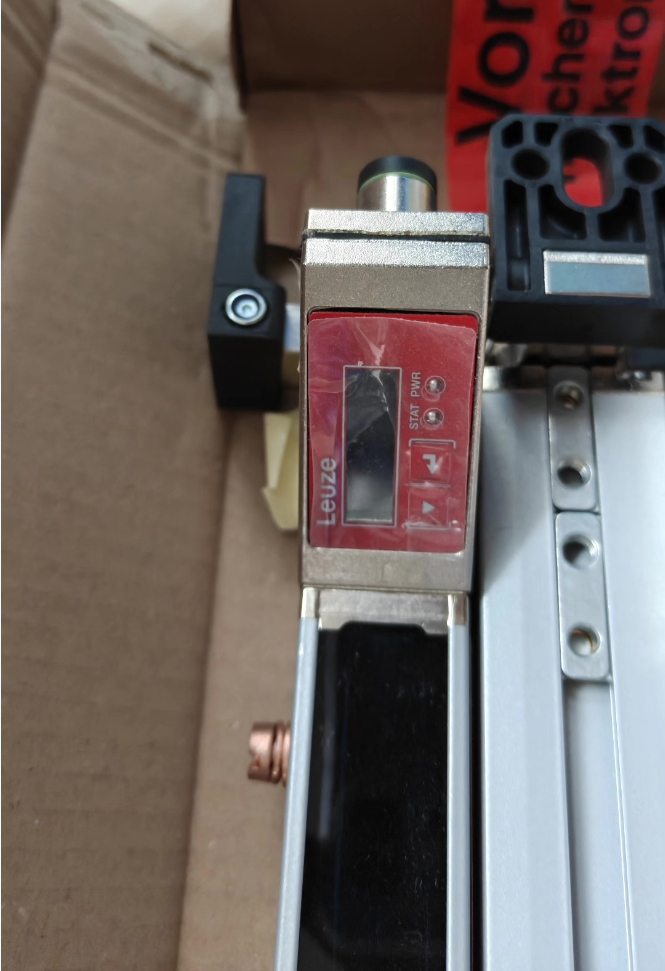

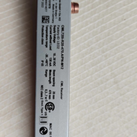
Número de artículo.: 50119370|Measuring light curtain transmitter (solo transmisor, debe usarse con el receptor emparejado)
✅ Explicación del código del modelo
| Campo | Descripción |
| CML720i | CML series measuring light curtain; 720i general-purpose measuring light curtain |
| t | Transmisor; R = Receiver |
| 5 | Beam pitch 5 milímetros |
| 240 | Effective measuring height 240 milímetros |
| A | A = Axial M12 connector (straight outlet); R = Rear outlet |
| M12 | conector M12, 5-pin A-coded |
📌 Key Technical Specifications
Principio: Infrared through-beam measuring light curtain, NOT safety light curtain. Used for dimension inspection, object contour detection, cálculo, material level monitoring and other measurement applications
Effective measuring range: 240 milímetros, total 48 vigas, beam pitch: 5 milímetros
Minimum detectable object diameter: 10 milímetros
Rango de operación: 0.1~3.5 m (guaranteed range)
Fuente de alimentación: DC 18~30V, reverse polarity & protección contra cortocircuitos
Cycle response time: 1.84 EM
fuente de luz: Infrared LED 940nm
Clase de protección: IP65
Temperatura ambiente: Operating -30℃ ~ +60℃; Storage -40℃ ~ +70℃
Alojamiento: Aluminum alloy profile, supplied with 2 BT-NC mounting sliders
Dimensión general: W29 × D35.4 × L315 mm
🔌 Electrical Interface (M12 5-pin male A-coded)
| Alfiler | Definición |
| 1 | FE Shield |
| 2 | V+ Power Positive |
| 3 | GND Power Ground |
| 4 | RS485 Tx+ |
| 5 | RS485 Tx- |
The transmitter only emits infrared beams. All communication and signal output are implemented on the receiver side. Optional receiver interfaces: CANabierto / Profinet / Enlace IO / Salida analógica
🧩 Matching Receiver Selection (Same spec: 240milímetros, 5mm beam pitch)
CML720i-R05-240.A/CN-M12: Autobús CANabierto
CML720i-R05-240.A/PB-M12: Profibus
CML720i-R05-240.A/PN-M12: Profinet
CML720i-R05-240.A/CV-M12: Analog voltage / current output
📋 Typical Applications
Altura / width measurement of objects on conveyor lines
Missing part inspection & contour detection for cartons
Material counting, gap detection
Detección de objetos transparentes (CML720i supports transparent part recognition)
Clasificación, embalaje, dimension inspection for timber & boards
⚠️ Distinción Importante
- CML720i = Measuring light curtain, no safety certification. Cannot be used for personnel safety protection; Safety light curtain series: MLC.
- Complete system = Transmitter (t) + Receptor (R) paired. Transmitter alone cannot work.
- Soportes 3 scanning modes: Parallel beam / Slanted beam / Cross beam, configurable via receiver.
Referencia del código HS
90314990 (Optical measuring sensor / photoelectric detection device)
Guía de solución de problemas
- Power ON, transmitter green LED steady ON: Normal; Brillante: Synchronization error (transmitter-receiver out of sync, falla de cableado)
- No signal: Check parallel installation of transmitter & receptor, operating distance ≤3.5m, no strong direct light on lens
- Inaccurate measurement: Lente limpia, verify beam mode setting, eliminate reflection interference
✅ Matching Receiver for CML720i-T05-240.A-M12 (Item No.50119370)
Model rule: CML720i-R05-240.A/xx-M12
R=Receiver; 05=5mm beam pitch; 240mm measuring height; A=Axial M12 straight connector; /xx = Interface suffix
| Complete Receiver Model | Número de artículo. | Tipo de interfaz |
| CML720i-R05-240.A/CN-M12 | 50119608 | CANabierto |
| CML720i-R05-240.A/PN-M12 | 50131878 | Profinet |
| CML720i-R05-240.A/PB-M12 | 50119609 | Profibus |
| CML720i-R05-240.A/CV-M12 | 50119610 | Cosa análoga (Voltaje / Actual) |
| CML720i-R05-240.A/L-M12 | 50119606 | Enlace IO |
Notas de selección
- Transmitter and receiver must be fully matched: 5mm beam pitch, 240mm measuring height, A-type axial M12 connector consistent with transmitter. Only receiver adds interface suffix /xx
- Transmitter only carries power & sync lines; All measurement output and bus communication are integrated in receiver
- Identical mechanical dimensions: W29 × D35.4 × L315 mm, supplied with 2 BT-NC mounting sliders
Cable Information
Sync cable between transmitter & receptor: M12 5-core, connects Transmitter ↔ Receiver
Receiver connects to PLC via separate bus / analog cable
Full Wiring for Eslogan CML720i (4 Interface Versions)
General architecture: Receiver X1 (8-pin M12 A-coded) main port: Fuente de alimentación + IO + sync line to transmitter; Transmitter X3 fixed as 5-pin M12 A-coded.
Transmitter Model: CML720i-T05-240.A-M12 (X3: 5-pasador M12)
Receiver X1【8-pin M12 A-coded】(Pin definition identical for all versions!)
✅ Receiver X1 (8-pin M12 A-coded, common for all variants)
| Alfiler | Señal | Observaciones |
| 1 | V+ DC24V | Poder positivo |
| 2 | I/O1 (Configurable) | Factory default: Teach input |
| 3 | GND 0V | Tierra eléctrica |
| 4 | C/Q IO-Link | Línea de comunicación IO-Link (reserved for CV/CN/PN versions) |
| 5 | I/O2 (Configurable) | Can be set as alarm / status output |
| 6 | RS485 Tx- | Sync signal between transmitter & receptor |
| 7 | RS485 Tx+ | Sync signal between transmitter & receptor |
| 8 | FE/Shield | Housing earth, shield connect to this pin |
✅ Transmitter X3 (5-pin M12 A-coded, fixed definition)
| Alfiler | Señal |
| 1 | FE Shield |
| 2 | V+ 24V |
| 3 | GND 0V |
| 4 | RS485 Tx+ |
| 5 | RS485 Tx- |
👉 Receiver X1 Pin1,Pin3,Pin6,Pin7 → Connect to Transmitter X3 Pin2,Pin3,Pin4,Pin5. Use Leuze Y-type sync cable, max length 20m.
1️⃣ CML720i-R05-240.A/PN-M12|Profinet Version
Receiver equipped with 3 M12 connectors:
X1: 8-alfiler (Fuerza + Sincronizar + IO, see table above)
X2: BUS IN (4-pin M12 D-coded)
X3: BUS OUT (4-pin M12 D-coded)
Profinet D-coded M12 (4-alfiler):
| Alfiler | Señal | Color del cable |
| 1 | TD+ | Amarillo |
| 2 | RD+ | Blanco |
| 3 | DT- | Naranja |
| 4 | RD- | Azul |
Wiring Architecture:
DC24V supplied to receiver X1; Sync cable from X1 to transmitter; Profinet bus connects PLC/switch to X2, X3 daisy-chains next PN device; Enable terminator resistor on last station.
Supports PLC reading: Blocked beam number, height value, diagnostic status.
2️⃣ CML720i-R05-240.A/CN-M12|CANopen Version
Receptor: X1 (8-alfiler, Fuerza + Sincronizar) + X2 (5-pin M12 A-coded CAN bus)
CAN bus X2 (5-pin M12 A-coded)
| Alfiler | Señal |
| 1 | FE Shield |
| 2 | NC Not Connected |
| 3 | CAN GND |
| 4 | CAN H |
| 5 | CAN L |
Alambrado: X1 power & sync to transmitter; CAN H/CAN L connect to CAN bus; 120Ω terminator resistor required at both ends of bus.
3️⃣ CML720i-R05-240.A/L-M12|IO-Link Version
Receiver only has X1 (8-pin M12 A-coded), no extra bus port. IO-Link multiplexes Pin4 (C/Q) of X1.
Pin1: 24V+
Pin3: 0V
Pin4: C/Q IO-Link communication → Directly connect to PLC IO-Link master port
Pin2/Pin5: Digital IO (Teach, fault output)
Pin6/7: Sync to transmitter
IO-Link master reads measured height and beam data directly, no extra bus cable required.
4️⃣ CML720i-R05-240.A/CV-M12|Analog Version (Voltaje / Actual)
Receiver also only has X1 (8-pin M12 A-coded), analog output on X1 Pin7.
Pin7: Analog OUT Analog Output
Parameter switchable: 0~10V or 4~20mA
Full scale corresponds to measuring height 0~240mm
Pin1/3: 24V fuente de alimentación
Pin6/7: Sync signal to transmitter
Pin2/Pin5: Digital IO (Falla / Teach)
⚠️ Nota: Analog output and RS485 sync share Pin7, internal auto switching. Wiring remains unchanged; voltage/current mode configured via Leuze software.
📌 General Wiring Guidelines
- Power supply range DC18~30V, Se recomienda CC 24 V.; Isolated power supply required, shield single-point grounding.
- Sync cable (Transmitter ↔ Receiver) max length 20m; Bus cable max 40m, shielded cable mandatory.
- Secuencia de cableado: Connect shield ground first → Wire all signals → Power ON; Power OFF before disassembly.
- IO1 default as Teach input, short to GND to trigger teach routine for zero calibration.
- Separate signal cables from power cables to avoid interference from frequency converters.
🧾 Quick Selection Guide
PLC Siemens: Prefer PN Profinet version
Industrial control system with CAN bus: CN CANopen
Compact PLC with IO-Link master: L IO-Link
Legacy equipment requiring analog acquisition: CV 4~20mA / 0~10V



NH42-63-318x560.png "Interruptores de transferencia automática tipo PC CHINT (ATS)NH42-63/4SZ")



