 contactor,cortacircuitos,sensor,Codificador,SOCIEDAD ANÓNIMA,Convertidor

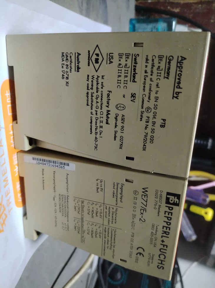

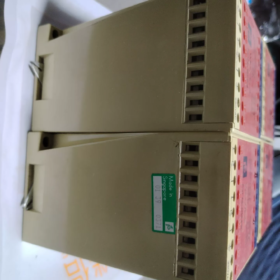
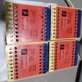
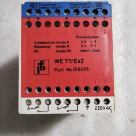
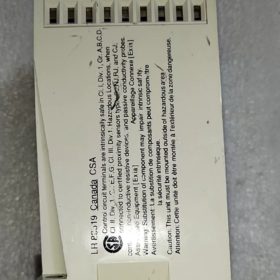
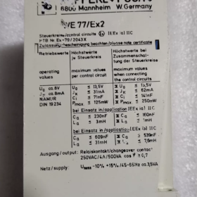
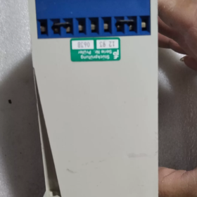
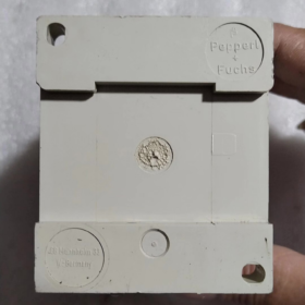
Pepperl+Fuchs WE77/Ex-2 Installation & Guía de cableado
WE77/Ex-2: Dual-channel NAMUR isolated switch amplifier (intrinsically safe barrier). Must be installed in safe-area control cabinet only. Blue terminals = intrinsically safe side (connect to field explosion-proof sensors). White/red terminals = non-intrinsically safe side (connect to SOCIEDAD ANÓNIMA and power supply).
Nombre del producto: Isolated Intrinsically Safe Switch Amplifier
Nota: WE77/Ex-2 is an obsolete legacy model. Recommended replacement for new projects: KFA6-SR2-Ex2
- Definición del código del modelo
WE77: Familia de productos, NAMUR switch amplifier
Ex: Intrinsically safe explosion-proof design
2: Dual-channel version (WE77/Ex-1 = single-channel)
Two power supply variants:
- WE77/Ex-2 115V: 115V AC supply
- WE77/Ex-2 230V: 230V (220V) Suministro de CA, most common in China
- Funciones principales
Intrinsically safe isolated barrier for NAMUR sensors and dry contact mechanical switches located in hazardous areas. It isolates and transmits binary switch signals from hazardous area to control system in safe area. Equipped with LB Lead Breakage detection, supports reverse operation mode. Each channel has independent relay change-over contact output.
Field side: Intrinsically safe circuit EEx ia IIC, suitable for Zone0/1/2 hazardous locations
Control side: Passive relay dry contact output (non-intrinsically safe)
Supported inputs: NAMUR proximity sensors (EN60947-5-6), passive mechanical contacts
- Especificaciones eléctricas clave
Intrinsically Safe Parameters (Field Side)
U₀: 13.5 En DC
I₀: 62 mamá
P₀: 125 mW
Explosion group: IIB / CII
Permitted external values: IIB: Co=0.929µF, Lo=5mH; CII: Co=0.23µF, Lo=3mH
NAMUR Input
Open circuit voltage ≈8V DC, short-circuit current ≈8mA
Switching threshold: 1.2~2.1mA, hysteresis approx.0.2mamá
Lead breakage detection: Fault alarm upon cable disconnection
Salida de relé (1 SPDT change-over contact per channel)
Calificación de contacto: 250V AC /4A; 24VDC/4A
Tiempo de respuesta: Pull-in ≈10ms, Drop-out ≈20ms
Frecuencia de conmutación máxima: <10Hz
Vida mecánica: 10⁷ switching cycles
Fuente de alimentación
230versión V: 198~253V AC, 45~65Hz; Power dissipation approx.2.5W
115versión V: 103.5~126V AC, 45~65Hz
- Mecánico & Datos ambientales
Dimensión: 40(W.) ×104(h) ×110(D) milímetros
Peso: approx.410g
Montaje: DIN rail clip mounting
Protección del recinto: IP20 (solo para instalación en gabinete)
Temperatura ambiente: -25℃ ~ +60℃
Terminales: Terminales de tornillo
- Información de certificación
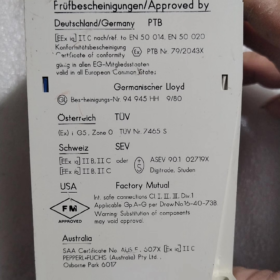
Certificado ATEX: PTB 02 ATEX 2065 / PTB Ex-79/2043X
Explosion marking: II (1) Dios [EEx ia] CII
- Asignación de terminales (WE77/Ex-2)
Channel1 field input: Terminal 1(-), 2(+)
Channel2 field input: Terminal 8(+), 9(-)
Channel1 relay output: 10/11/12 (change-over contact)
Channel2 relay output: 13/14/15 (change-over contact)
Fuente de alimentación: 17, 18
- Solicitud
Químico, farmacéutico, aceite & lugares peligrosos por gas: Signal isolation for NAMUR proximity sensors, explosion-proof limit switches, explosion-proof level switches. Relay signals are sent to PLC/DCS DI modules.
- Piezas de repuesto & Notas de reemplazo
- WE77/Ex-2 no longer recommended for new projects by manufacturer. Reemplazo directo: KFA6-SR2-Ex2 (dual-channel NAMUR safety barrier, salida de relé, equivalent function, smaller footprint)
- For maintenance of existing systems: Only surplus / stock spare parts available. Confirm 115V or 230V variant before procurement, the two versions are not interchangeable.
- Single-channel equivalent: WE77/Ex-1, replacement KFA6-SR1-Ex
- Solución de problemas comunes
- No input response: Check for LB lead breakage alarm on NAMUR loop; verify external capacitance/inductance does not exceed intrinsic safety limits
- Relay fails to switch: Confirm power supply variant matches device rating; verify input current falls within NAMUR operating range
- Frequent false lead breakage alarm: Excessive cable length with high distributed capacitance/inductance, or damaged cable insulation
- Instalación Mecánica
- Carril DIN: Montaje en carril DIN estándar de 35 mm. Hook top clip onto rail, press module down to lock. para eliminar: Lift bottom latch and pull outward.
- Entorno operativo
Temperatura ambiente: -25℃ ~ +60℃, cabinet ventilation required; mantener alejado de fuentes de calor, vibration and corrosive gas
Protection class IP20, indoor cabinet use only, not for open or humid direct exposure
Mounting clearance: Small gaps between adjacent modules recommended for heat dissipation
- Mandatory Explosion Protection Rules
✅ Unit must be mounted in safe area, NEVER install in Zone0/1/2 hazardous areas
✅ Intrinsically safe cables (azul) and non-intrinsically safe cables (fuerza, salida de relé) must run in separate trunking/conduits, cannot share same conduit
- Terminal Table
| Terminal Group | Número de terminal. | Descripción | Circuit Classification |
| Channel1 Field NAMUR Input (Blue IS Terminals) | 1(-), 2(+) | Channel1: NAMUR proximity sensor / explosion-proof dry contact | Intrinsically safe EEx ia IIC |
| Channel2 Field NAMUR Input (Blue IS Terminals) | 8(+), 9(-) | Channel2: NAMUR proximity sensor / explosion-proof dry contact | Intrinsically safe EEx ia IIC |
| Channel1 Relay Change-over Output | 10, 11, 12 | 11 Común, 10 NC normalmente cerrado, 12 NO normalmente abierto | Non-intrinsically safe relay |
| Channel2 Relay Change-over Output | 13, 14, 15 | 14 Común, 13 NC normalmente cerrado, 15 NO normalmente abierto | Non-intrinsically safe relay |
| Fuente de alimentación | 17, 18 | Entrada de alimentación de CA: Select 115V /230V variant, no intercambiables | Non-intrinsically safe |
Importante: NAMUR field wiring is polarity sensitive. Reversed polarity will trigger LB lead breakage fault and unit malfunction.
- Wiring Schemes
Esquema 1: NAMUR Proximity Sensor (Más común)
Channel1: 2-wire NAMUR sensor → Terminals 1(-), 2(+)
Channel2: 2-wire NAMUR sensor → Terminals 8(+), 9(-)
NAMUR loop includes LB lead breakage monitoring: Cable break, short circuit or reversed polarity will trigger channel fault LED.
Esquema 2: Explosion-proof Passive Dry Contact (Interruptor de límite)
Dry contact directly connected to IS terminals, lead breakage detection remains active. No external supply for contact; WE77/Ex-2 provides approx.8V/8mA IS drive internally.
Relay Output Wiring (to PLC DI)
Each channel is SPDT passive change-over contact, no external supply required
Channel1: 11 Común, 12 NO, 10 CAROLINA DEL NORTE
Channel2: 14 Común, 15 NO, 13 CAROLINA DEL NORTE
Contact maximum rating: 250V y / 4A; 24VDC /4A. Do not overload to avoid contact burnout.
Cableado de energía
Terminales 17 & 18 for AC supply:
WE77/Ex-2 230V version: AC 198~253V (Mainland China standard)
WE77/Ex-2 115V version: AC 103.5~126V
⚠️ Hardware differs between two power versions, NOT interchangeable.
- Selección de cables (Explosion Compliance Mandatory)
- Intrinsically safe side (Blue terminals to field instrument): Blue IS cable recommended, conductor cross-section ≥0.5mm², rated voltage ≥500V
- Intrinsically safe loop must be verified for maximum permitted cable capacitance Co and inductance Lo:
IIC application: Co ≤0.23µF, Lo ≤3mH
IIB application: Co ≤0.929µF, Lo ≤5mH
Excessive cable length causes distributed capacitance/inductance over-limit, invalidating intrinsic safety certification.
- Shielded cable: Shield single-point earthed at control room end, shield floating at hazardous area side to prevent earth loop current.
- Procedimiento de cableado (Safety Sequence)
- Apagar! Isolate all power sources and confirm zero voltage before wiring
- Connect field intrinsically safe cables first (blue terminals), verify polarity
- Connect relay output cables to PLC DI modules
- Connect module power terminals 17 &18 last
- Apriete todos los terminales de tornillo, no loose strands or exposed copper causing short circuit
- Pre-power check: IS cables separated from power cables, no mixed routing
- Power-on commissioning: Power on without field load first and check channel LEDs. Connect field sensors, test switching action and LB fault function.
- Puesta en servicio & Indicación LED
Independent LED per channel: Illuminated when valid input signal present; LB lead breakage fault will extinguish LED / trigger fault alarm
Modo de operación: Reversible mode available (relay de-energizes when input activates), configurable per project requirement
Lead breakage test: Disconnect field sensor wire, module shall detect line fault and activate LB alarm.
- Critical Prohibitions & Errores comunes
- ❌ Megger insulation test is forbidden on intrinsically safe terminals! High voltage from megger will destroy internal IS circuit and permanently damage unit. Remove all IS wiring before any cable high voltage test.
- ❌ Never route 220V power cables or non-IS signal wires into blue intrinsically safe terminals; intrinsic safety protection will be destroyed.
- ❌ IS circuits and non-IS circuits cannot share same cable or trunking.
- ❌ Do not install WE77/Ex-2 in hazardous area.
- ❌ Do not exceed Co/Lo intrinsic safety limits, explosion certification will be invalid.
- ❌ Do not overload relay contacts; damaged relay contacts cannot be repaired separately, full module replacement required.
- Earthing Instruction
WE77/Ex-2 is transformer-isolated safety barrier; galvanic isolation between IS side and control side. Module housing connected to cabinet protective earth as standard, resistencia de tierra ≤4Ω. Isolated barrier does NOT require dedicated intrinsic safety earth like zener barriers.
- Post Power-On Quick Fault Diagnosis
- No LED illumination after power-up: Check voltage at terminal 17/18, confirm 115V/230V model match, check loose power terminals.
- Persistent LB fault alarm: ①NAMUR polarity reversed; ②broken cable; ③cable distributed capacitance/inductance over-limit; ④field sensor damaged.
- Sensor switches but relay does not toggle: Verify NAMUR current within operating range; check NO/NC contact selection.
- Unintended relay chattering/false switching: Power fluctuation, interferencia electromagnética. Use shielded cable and separate strong/weak signal wiring.
WE77/Ex-2 Intrinsically Safe Blue Terminals & Non-Intrinsically Safe Relay Terminal Current Parameters
Distinguish between intrinsic safety certified maximum short-circuit current Io (explosion parameter) and NAMUR normal operating current. Non-intrinsically safe side is relay contact rated current.
🔵 Blue Terminals: Intrinsically Safe Field Input Side
WE77/Ex-2 230V version (Mainland China mainstream)
- Intrinsic safety maximum short-circuit current Io = 62mA (certified explosion parameter. In short-circuit condition, module limits output current below this value to maintain explosion safety)
- NAMUR normal operating current: Open circuit ≈8V DC, static short-circuit current ≈8mA; Switching threshold 1.2~2.1mA per NAMUR standard
Note for 115V WE77/Ex-2 variant: Io=31mA. Always confirm power supply version during selection.
⚠️ Importante: 62mA is the safety limit short-circuit current, NOT normal working current. Under normal NAMUR sensor operation, loop current is only a few milliamps.
⚪ White Terminals: Non-intrinsically Safe Relay Output (Terminales 10/11/12,13/14/15)
SPDT change-over contact rated load current (carga resistiva) per channel
CA 250 V: 4A (cosφ>0.7)
CC 24 V: 4A
DC 60V: 0.6A
CC 220 V: 0.1A
Max contact power rating: 500Virginia; Overload will cause contact erosion, module non-repairable.
Adicional: Module Power Terminals (17,18)
Total power dissipation approx.2.5W. For 230V AC supply, power loop current is low, aprox.0.01A.
Summary Table
| Terminal Group | Artículo | Valor | Observaciones |
| Blue IS Terminals (230modelo V) | Intrinsic safety limit short-circuit current Io | 62mamá | Explosion protection short-circuit limit |
| Blue IS Terminals | NAMUR normal short-circuit current | ≈8mA | NAMUR sensor operating current |
| White Non-IS Relay Contacts | Rated current at AC250V / CC 24 V | 4A | Carga resistiva, independent per channel |




NH42-63-318x560.png "Interruptores de transferencia automática tipo PC CHINT (ATS)NH42-63/4SZ")



