 contactor,cortacircuitos,inversor solar,medidor electrico,baterias solares


1.Basic Model Information
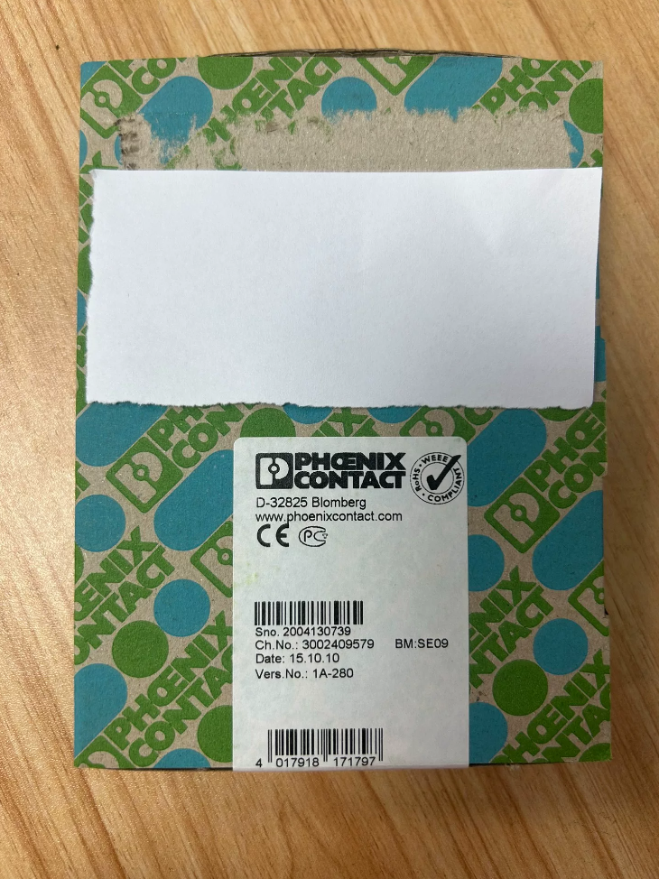
Nro. de orden: 2744429
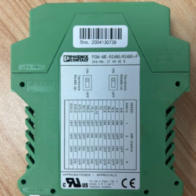
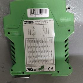
Modelo completo: PSM-ME-RS485/RS485-P
Tipo de producto: RS485 Isolated Repeater (Bus Signal Amplifier / Segment Isolator)
Origen: Alemania
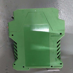
Montaje: Standard DIN 35 mm rail mounting
Housing Dimensions: W. 22.5 mm × H 99 mm × D 114.5 milímetros, Protección IP20
Material de la carcasa: Flame-retardant PA6.6, Green RAL6021
- Funciones principales
- 3-way Galvanic Isolation: Power Side ↔ Segment A Bus ↔ Segment B Bus, completely eliminating ground loop interference, surge and common-mode noise.
- Bus Segmentation & Capacity Expansion: máx.. 32 nodes per single RS485 segment; each segment supports independent 32 nodes after repeater connection. Arriba a 9 units cascaded at low baud rates.
- Extended Transmission Distance: Estándar 1200 metro (twisted pair; lower baud rate corresponds to longer transmission distance).
- Compatible Bus Protocols: Modbus RTU, PROFIBUS-DP, general 2-wire RS485 half-duplex bus.
- Automatic Direction Control: No external RTS/CTS required; hardware auto transmit/receive switching.
- Especificaciones eléctricas
3.1 Fuente de alimentación
Tensión nominal: 24 V AC/DC ±20%
Consumo de energía típico: 90 mA @ 24 VCC, máximo. 100 mamá
Isolation Withstand Voltage: ≥2.5 kV AC between power supply and buses, and between two bus segments.
3.2 Interfaz de comunicación (Dual 2-wire RS485 Half-duplex)
Baud Rate Range: Full coverage from 4.8 kbps to 1500 kbps
4.8 / 9.6 / 19.2 / 38.4 / 57.6 / 75 / 93.75 / 115.2 / 187.5 / 375 / 500 / 1500 kbps
Frame Format: Switchable 10-bit / 11-poco, NRZ UART encoding
Signal Delay: Bit delay < 200 ns, signal distortion < 1.5%
Termination Resistor: Incorporado 220 Oh + 390 Ω switchable via DIP switch
Bloque de terminales: Screw pluggable terminals, cable cross-section 0.2~2.5 mm² (AWG24~14)
3.3 Parámetros ambientales
Temperatura de funcionamiento: -40 ℃ ~ +70 ℃ (Wide-temperature industrial grade)
Almacenamiento / Temperatura de transporte: -40 ℃ ~ +85 ℃
Humedad: 10%~95% non-condensing, máximo. altitud 5000 metro
Vibración / Resistencia a los golpes: 5 g vibration, 25 g shock, compliant with IEC industrial standards.
- Certificaciones & Aprobaciones
General Certifications: CE, UL, cUL, RoHS, CAO, DNV GL Marine Approval
Explosion Protection: ATEX II 3G Ex ec IIC T4 Gc (Suitable for hazardous areas)
CEM: Full set of EN61000 anti-interference standards (ESD, aumento, RF radiation)
- Escenarios de aplicación típicos
- Multi-instrument Modbus networking in factories; segmented isolation when node quantity exceeds 32.
- Long-distance cross-workshop PROFIBUS-DP wiring to eliminate ground potential difference.
- Mixed high/low voltage control cabinets; isolate RS485 bus from inverter interference.
- Signal extension for field bus in chemical & oil/gas hazardous areas.
- Building automation, long-distance remote PLC RS485 acquisition sub-stations.
- Referencia de modelo alternativo
Cost-effective non-explosion-proof variant of same series: PSM-ME-RS485/RS485 (without ATEX, different order number)
Fiber-optic isolated version: PSM-ME-RS485/FO, alternative for long-distance heavy electromagnetic interference scenarios.
- Key Operation Guidelines
- Termination resistors must be enabled via DIP switches at both physical ends of each bus segment respectively.
- Use shielded twisted pair for bus wiring; single-point grounding for shield layer.
- Maximum cascade limit: Arriba a 9 units at 4.8~93.75 kbps; reduce cascade quantity for high baud rates.
- Three independent isolation channels allow connection to devices with different ground potentials to avoid communication dropouts.
Official Installation Manual for Fénix Contacto 2744429 (PSM-ME-RS485/RS485-P)
Basic Document Information
Nro. de orden: 2744429
Nombre completo del modelo: PSM-ME-RS485/RS485-P
Tipo de producto: 3-way Isolated RS485 Repeater (with ATEX explosion-proof certification)
Mounting Standard: TU ÚNICO 60715 Riel estándar TH35
Clase de protección: IP20 (Indoor cabinet use only)
Applicable Environment: -40 ℃ ~ +70 ℃, sin condensación, free of dust and water accumulation.
- Preparación previa a la instalación
1.1 Lista de herramientas
Flat-blade screwdriver (2.5 milímetros), torque screwdriver, rail end stop (E/NS35 N, Número de pedido. 0800886), shielded twisted pair cable, multímetro.
1.2 Cable Specifications
Terminales de potencia: 0.2~2.5 mm² solid / stranded copper wires
RS485 Bus: Dedicated shielded twisted pair (0.5~0.75 mm² recommended)
Terminal Tightening Torque: 0.5~0.6 N·m (5~7 lb-in)
1.3 Installation Environment Prohibitions
- Do not mount directly under inverters, contactors or high-power transformers (blocked heat dissipation air duct + electromagnetic interference).
- Reserve ≥25 mm ventilation gap above and below the module.
- Keep away from 380 V power cables; separate trunking for power and signal cables.
- Strictly comply with ATEX II 3G Ex ec IIC T4 Gc zoning regulations for hazardous area installations.
- DIN Rail Mechanical Installation Procedures
2.1 Mount Module onto DIN Rail
- Fix clean, rust-free standard TH35 DIN rail on cabinet backplate.
- Hook the upper latches of the module onto the top edge of the rail.
- Press the bottom of the module forward until a click sound indicates full locking.
- Install rail end stops on both sides of the module to prevent sliding during operation.
2.2 Module Removal Steps
- Pry down the bottom locking tab of the module with a flat-blade screwdriver.
- Gently pull the lower part of the module outward.
- Lift upward to disengage the upper latches from the rail for removal.
2.3 Mechanical Installation Notes
Do not strike or force plug/unplug the module to prevent damage to internal isolation circuits.
Install shock-absorbing mounting brackets for cabinet rails in high-vibration equipment (stamping, minería).
Only horizontal transverse mounting is permitted; vertical upside-down installation is forbidden.
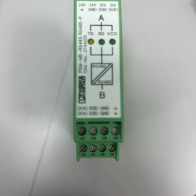
3.2 Standard Wiring Rules (2-wire Half-duplex Modbus / PROFIBUS)
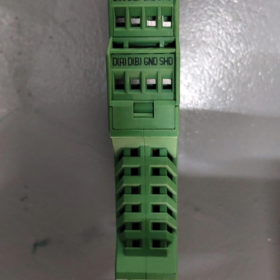
- Strictly match bus polarity one-to-one: A1 connects to device A of upstream equipment, B1 connects to device B of upstream equipment; A2 connects to substation A of downstream equipment, B2 connects to substation B of downstream equipment.
- Shield layer of shielded twisted pair: Single-point grounding at both physical ends of the bus. Unify G1/G2 terminals of intermediate repeaters to FE terminal for central single-point grounding. Strictly prohibit double-ended grounding which forms ground loops.
- Power wiring: L+ and Lcannot be reversed. Built-in reverse polarity protection exists, yet long-term reverse connection will shorten service life.
- Do not short-circuit A/B terminals or mix power and bus terminals; short circuits will burn isolation circuits.
3.3 Mandatory Wiring Requirements for Hazardous Areas
- Use explosion-proof shielded cables with cable glands complying with Ex ec standard.
- Reliably connect FE earth bar to protective earth of explosion-proof cabinet; ground resistance < 4 Oh.
- No mid-bus tapping; termination resistors can only be installed at the two physical ends of the bus.
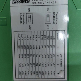
- DIP Switch Configuration Operation
4.1 DIP Switch Location
Pry open the plastic side cover of the module; two groups of DIP switches are inside:
- T1: Termination resistor for Segment A bus (220 Oh + 390 Ω voltage divider matched to 120 Ω bus)
- T2: Termination resistor for Segment B bus
4.2 DIP Switch Application Rules
EN: Enable built-in termination resistor; APAGADO: Disable termination resistor.
Only set the DIP switch to ON for devices/repeaters at the physical extreme ends of the bus; set all intermediate nodes to OFF.
Escenarios típicos:
- PLC at the start of Segment A bus, this repeater at Segment A end → S1=ON
- Last instrument at the end of Segment B bus → S2=ON
- Repeater only used as intermediate segment divider with other terminals at both ends of two bus segments → S1 and S2 both OFF
4.3 Transmission Rate Adaptation Note
This model features hardware auto-adaptation from 4.8 kbps to 1500 kbps; no baud rate DIP switch required. Hardware auto transmit/receive switching without RTS control signal.
- Power-on Commissioning Steps
- After wiring completion, measure voltage between L+/Lwith multimeter: 19.2~28.8 V (24 V ±20%), sin cortocircuito.
- Power on without load; steady green power indicator light means normal operation. If off, inspect power supply circuit.
- Bus communication test:
Flashing DATA indicator during data transmission indicates normal signal forwarding.
No flashing: Check reversed A/B polarity, mismatched termination resistor setting or broken bus cable.
- Communication packet loss troubleshooting: Inspect shield grounding, separation of power & signal cables and termination resistor configuration.
- Electrical Isolation Safety Instructions (Centro)
The module adopts three independent isolation channels: Power ↔ Bus A ↔ Bus B, with isolation withstand voltage of 2.5 kV CA.
- Supports connection of two bus segments with different ground potentials to eliminate ground potential difference interference.
- Isolates bus segments connected to inverters and high-power motors, preventing surge breakdown of PLC communication ports.
- Provides physical isolation between hazardous area bus and control room bus to meet Ex safety clearance requirements.
- Installation Acceptance Criteria
- Mecánico: Module fixed without looseness, latches fully engaged, rail end stops installed properly.
- Alambrado: All terminals tightened to 0.5~0.6 N·m, no bare copper exposed, no insulation trapped under terminals.
- Toma de tierra: FE terminal reliably connected to cabinet protective earth, single-point shield grounding without ground loops.
- DIP Switch: Termination resistors only enabled at bus two ends, all intermediate nodes disabled.
- Power-on: Steady power indicator light, normal flashing of communication indicator during data transmit/receive.
- Ambiente: Unobstructed ventilation above and below module, kept away from strong electromagnetic interference sources.
- Installation Fault Troubleshooting Matrix
| Fenómeno de falla | Root Installation Cause | Rectification Action |
| Indicador de encendido apagado | Reversed L+/L-, insufficient supply voltage, loose terminals | Reverse power polarity, measure voltage, retighten terminals |
| Fallo total de comunicación | Reversed A/B polarity, broken bus cable, all termination resistors enabled | Swap A/B wiring, conduct cable continuity test, enable resistors only at bus two ends |
| Frequent packet loss at high baud rates | Double-ended shield grounding, mixed power & signal trunking, missing termination resistors | Conexión a tierra de blindaje de un solo punto, separate cable routing, set DIP switches to ON at bus two ends |
| Unstable communication in hazardous areas | Excessive ground resistance, non-ex-certified cables | Rebuild earth bar, replace with Ex-certified shielded cables |
| Severe module overheating | No upper/lower ventilation gap, adjacent high-power power supplies | Reservar 25 mm gap top and bottom, relocate away from heat-generating components |
- Cumplimiento & Requisitos de mantenimiento
- Certificaciones: CE, UL, ATEX, DNV GL, RoHS; retain certification documents for hazardous area projects.
- Periodic Maintenance (Cada 6 Meses):
Inspect terminal torque to prevent loosening caused by thermal expansion & contraction.
Clean dust on module surface to guarantee ventilation.
Re-test ground resistance and confirm intact shield grounding.
- Modification Prohibitions: Do not remove isolation circuits, short isolation terminals or replace with non-original terminal accessories.
Cross-brand Model Comparison Table for Phoenix Contact 2744429 (PSM-ME-RS485/RS485-P)
Core Features of Reference Product (Replacement Matching Criteria)
- 3-way isolation: Power ↔ Bus A ↔ Bus B, 2.5 kV AC isolation rating
- 2-wire RS485 half-duplex, auto TX/RX switching, compatible with Modbus / PROFIBUS
- DIN35 rail mounting, wide temperature range -40~+70 ℃, built-in switchable termination resistors
- Amplia gama 24 V AC/DC power supply, narrow 22.5 mm housing width
- Factory-certified ATEX II3G explosion protection (Key distinguishing factor)
- Direct Replacements from Top European Industrial Automation Brands (Preferred for Standardized Projects)
1.1 Weidmüller (Explosion-proof Isolated Repeater with Same Positioning)
| OEM Model | Matching Rate | Diferencias fundamentales | Escenarios aplicables |
| 7760054321 | 95% | 3-way isolation, ATEX explosion-proof, 24 VCA/CC, 22.5 mm carcasa; max baud rate limited to 500 kbps (1500 kbps for Phoenix Contact) | Chemical hazardous areas, general Modbus/PROFIBUS; fully interchangeable for low-speed buses |
| 7760054322 (No a prueba de explosiones) | 90% | No ATEX certification; all other electrical parameters identical | Indoor standard control cabinets without hazardous area requirements |
1.2 siemens
| OEM Model | Matching Rate | Diferencias fundamentales | Escenarios aplicables |
| 6ES7972-0AA02-0XA0 PROFIBUS Repeater | 70% | PROFIBUS-only, prone to Modbus packet loss; 2-way isolation without independent 3-way isolation; no ATEX | Dedicated to pure DP bus; direct replacement not recommended for Modbus |
| 6ES7972-0CB20-0XA0 (Universal Isolated Repeater) | 82% | 3-way isolation, 1.5 mbps; no explosion protection, wider 45 mm carcasa | Siemens complete cabinet systems, non-hazardous zones |
1.3 Electricidad Schneider
| OEM Model | Matching Rate | Diferencias fundamentales | Escenarios aplicables |
| TSXCSU01 | 80% | 2-way isolation without independent 3-way isolation; no ATEX; máximo 500 kbps | Supporting legacy Modbus PLCs, low-interference environments |
| XPSM-RS485-ISO | 88% | 3-way isolation, auto TX/RX; no explosion protection, 27 mm carcasa | General building automation, water treatment non-hazardous projects |
1.4 TEJIDO
| OEM Model | Matching Rate | Diferencias fundamentales | Escenarios aplicables |
| RS485-REP-ISO | 85% | 3-way isolation, 1.5 mbps; no explosion protection, 35 mm wide housing | Standard control cabinets matched with ABB DCS |
- Cost-effective Alternatives from Domestic Industrial Communication Brands (Cost-down Projects)
2.1 Advantech
| Modelo | Matching Rate | Diferencias | |
| ADAM-4510S (Isolated Version) | 83% | 2-way isolation without independent 3-way isolation; no ATEX; rail-mounted | General factory Modbus data acquisition, non-hazardous zones without severe ground loops |
2.2 Moxa
| Modelo | Matching Rate | Diferencias | |
| TCC-80I | 86% | 3-way isolation, 1.5 mbps; no ATEX; 30 mm housing width | Líneas de producción automatizadas, remote sub-stations, non-hazardous areas |
2.3 Mornsun (DIN Rail Isolated Repeater)
| Modelo | Matching Rate | Diferencias | |
| UR485-REP | 80% | 3-way isolation, 2.5 kV withstand voltage; no explosion protection, bajo costo | Low-voltage complete sets, small equipment matching |
- Internal Phoenix Contact Replacements (OEM Spare Parts, Zero Rewiring)
- 2744416 PSM-ME-RS485/RS485 (No P Suffix)
Matching Rate: 99%
Diferencia: No ATEX explosion-proof certification; terminales, interruptores DIP, dimensions and electrical performance fully identical
Sugerencia de reemplazo: Direct swap in non-hazardous zones without wiring modification
- PSI-REP-RS485W2 (Número de pedido. 2313096)
Matching Rate: 85%
Diferencia: 4-way isolation, wider housing, enhanced surge protection, precio más alto; suitable for heavy-interference high-power workshops
- Replacement Selection Grading Recommendations
Calificación 1: Fully Seamless Replacement (Priority for Hazardous Area Projects)
Weidmüller 7760054321
3-way isolation + ATEX explosion-proof, narrow 22.5 mm carcasa, consistent terminal logic; universal wiring, installation and DIP switch rules, only slightly lower max baud rate for high-speed buses.
Calificación 2: OEM Equivalent for Non-hazardous Zones (Optimal Cost)
Contacto Fénix 2744416 (Same brand non-explosion-proof variant)
Identical cabinet cutout size, terminal layout and termination resistor DIP switch; plug-and-play replacement without program modification.
Calificación 3: Compatible Replacement for Siemens Complete Cabinet Projects
6ES7972-0CB20-0XA0
Supports dual DP & Modbus protocols, 3-way isolation; only wider housing requires reserved cabinet space.
Calificación 4: Low-cost General Industrial Replacement (No peligroso, Low Interference)
Moxa TCC-80I / Advantech ADAM-4510S
Not recommended for hazardous areas, inverter-dense workshops or sites with large cross-equipment ground potential differences.
- Advertencias de riesgo de reemplazo (Diferenciadores clave)
- ATEX Explosion Protection: Only Phoenix Contact 2744429 and Weidmüller 7760054321 carry explosion-proof certification; all other models cannot be deployed in Ex zones, causing compliance failure if substituted.
- Independent 3-way Isolation: Siemens 6ES7972-0AA02 and Advantech ADAM-4510 only provide 2-way isolation, prone to communication dropouts when crossing large ground potential differences.
- Max Baud Rate: Weidmüller explosion-proof model capped at 500 kbps vs. original 1500 kbps; caution for high-speed Profinet / high-speed Modbus applications.
- Housing Width: siemens, ABB and Moxa units mostly 30~45 mm wide; rail layout adjustment required for original 22.5 mm narrow installation slots.


 Sensor de proximidad capacitivo CCN15-30GS60-E2-V1")


")
NH42-63-318x560.png "Interruptores de transferencia automática tipo PC CHINT (ATS)NH42-63/4SZ")


