 Contacteur,disjoncteur,onduleur solaire,compteur électrique,batteries solaires

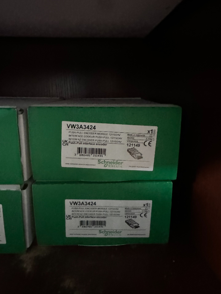

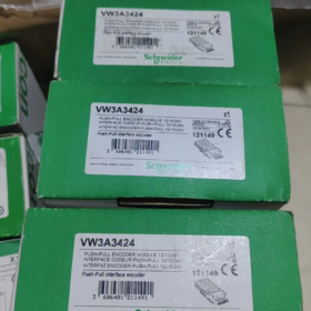
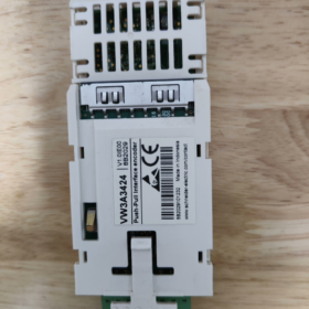
The VW3A3424 is an HTL (High Threshold Logic) incremental encoder interface option card developed by Schneider Électrique exclusively for Altivar series variable speed drives, serving as an expansion accessory for closed-loop drive control. This module feeds speed/position feedback signals from an external encoder into the drive to implement Flux Vector Control (FVC) with sensor feedback and Synchronous Motor Vector Control (FSY). It greatly improves low-speed torque output, speed regulation accuracy, dynamic response performance and torque control precision, making it suitable for industrial drive applications demanding stable speed regulation and high positioning accuracy.
- Model Coding Breakdown
| Segment de code | Description |
| VW3A | General accessory prefix for Schneider Altivar series drives, representing drive option components |
| 34 | Product family code for encoder interface modules, identifying the range of encoder feedback options |
| 24 | Specific model identifier, denoting the HTL level variant supporting wide-range 12–24 V power supply for incremental encoders |
III. Spécifications techniques de base
| Élément de paramètre | Spécification |
| Type de produit | HTL incremental encoder interface module |
| Compatible Drive Series | Altivar Machine ATV340, Altivar Process ATV900 (including ATV930/ATV950), modular Altivar Process drives |
| Encoder Supply Voltage | 12 À DC / 15 À DC / 24 À DC (adaptive output, no hardware DIP switch configuration required) |
| Maximum Supply Current | 0.2 A @ 12 V; 0.175 A @ 15 V; 0.1 A @ 24 V |
| Supported Signal Types | Push-pull differential (UN / /UN, B / /B), push-pull single-ended (UN, B), open-collector differential (UN / /UN, B / /B), open-collector PNP/NPN single-ended (UN, B) |
| Fréquence de fonctionnement maximale | 12 kHz |
| Maximum Transmission Distance | 500 m (subject to matching wire gauge and signal type) |
| Méthode de connexion | 1 channel detachable spring-cage terminal block |
| Fonctions de protection | Protection contre les courts-circuits, protection contre les surcharges |
| Poids net | 0.15 kilos |
| Installation Slot | Drive Slot B (dedicated left-hand option slot for encoder interfaces / IO relays) |
- Terminal Pin Assignment
The module adopts an 8-pin spring-cage terminal block plus a dedicated shield terminal. Pin definitions are listed below:
| Numéro de broche. | Signal Label | Description de la fonction |
| 1 | A+ | Encoder Channel A positive signal input |
| 2 | UN- | Encoder Channel A negative signal input (/UN) |
| 3 | B+ | Encoder Channel B positive signal input |
| 4 | B- | Encoder Channel B negative signal input (/B) |
| 5 | V+ | Encoder power supply positive terminal (adaptive 12/15/24 Sortie V) |
| 6 | V+ | Encoder power supply positive terminal (redundant parallel terminal) |
| 7 | 0V | Encoder power supply reference ground |
| 8 | 0V | Encoder power supply reference ground (redundant parallel terminal) |
| BOUCLIER | Cable Shield | Overall shield termination for signal cable; connect to the drive cabinet earthing plate nearby |
- Installation, Commissioning and Configuration
- Hardware Installation Specifications
Install the module into the left-hand Slot B option slot (dedicated for encoder interfaces / IO relays) only when the drive is fully powered off, and confirm the latches are fully locked.
Use shielded twisted-pair cable for encoder wiring; route cables away from power cables and reliably earth the shield at one end only to avoid electromagnetic interference.
When only single-ended signals are used, terminate unused differential negative pins according to encoder type: connect unused negative pins to 0V for push-pull / PNP encoders; connect unused negative pins to V+ for NPN encoders.
- Parameter Configuration Steps (ATV900 / ATV340 Series)
- Navigate to the drive menu [Complete Settings] → [Encoder Configuration], select the corresponding encoder interface, and set encoder PPR count, signal type and supply voltage parameters.
- Enter all rated motor nameplate parameters and perform motor autotuning.
- First set [Encoder Usage (EnU)] à “Non”, jog the motor at low speed for several seconds, and enable encoder feedback only after the status of [Encoder Detection (EnC)] changes to “Completed”.
- Set the motor control type parameter [Ctt] to Flux Vector Control (FVC) for asynchronous motors or Synchronous Motor Vector Control (FSY) for synchronous motors to activate closed-loop operation.
- Matrice de dépannage des pannes courantes
| Symptôme de panne | Analyse des causes profondes | Step-by-Step Remedial Actions |
| Encoder detection fails (abnormal EnC status) | 1. Reversed A/B phase wiring or poor shield earthing | 1. Verify terminal wiring sequence and check shield earthing integrity |
| 2. Mismatch between encoder supply voltage and load current | 2. Confirm encoder power consumption and match the module output voltage range | |
| 3. Incorrect encoder PPR parameter setting | 3. Correct the PPR setting and re-run the detection routine | |
| Severe speed fluctuation and unstable torque output | 1. Signal attenuation and distortion caused by overlong cables | 1. Shorten cable length or increase wire gauge; ensure cable length does not exceed the 500 m limite |
| 2. Encoder signals subject to heavy electromagnetic interference | 2. Adjust cable routing and reliably earth the shield at one end only | |
| 3. Eccentricity or misalignment from improper mechanical encoder mounting | 3. Recalibrate encoder coaxial alignment and fasten mounting screws | |
| No module output, encoder unpowered | 1. Poor slot contact or incompletely inserted module | 1. Éteindre, re-seat the module and confirm slot latches are fully locked |
| 2. Short-circuit on encoder side triggering overload protection | 2. Troubleshoot short-circuit faults on encoder wiring and power cycle the drive for reset |
VII. Cross-Series Encoder Module Comparison
| Modèle | Type d'encodeur | Différences fondamentales |
| VW3A3424 | HTL incremental | Wide 12–24 V supply, maximum 500 m transmission distance, maximum 12 kHz frequency, compatible with general industrial HTL encoders |
| VW3A3420 | Durée de vie / FinDat 2.2 / SSI | Supports digital absolute encoders, maximum 1000 kHz frequency, max cable length 100 m, suitable for high-precision positioning applications |
Complete Parameter Navigation List for Drives with VW3A3424
Conditions préalables:
- Set the drive access level to Full Access first; sinon, some advanced parameters will be hidden.
- Core control mode and encoder parameters must be modified with the drive stopped; changes do not take effect during operation.
- The ATV340 series requires firmware version ≥ V1.5IE10 for VW3A3424 compatibility.
- Parameter Navigation for ATV900 Series (ATV930/ATV950/ATV960/ATV980)
- Basic Motor Parameters (Mandatory before Autotuning)
Menu Path: Main Menu → Complete Settings → Motor Control → Motor Parameters
| Code de paramètre | Nom du paramètre | Configuration Instruction |
| bFr | Standard Motor Frequency | Select per motor nameplate; factory default 50 Hz IEC |
| nPr | Motor Rated Power | Set strictly to the value marked on the motor nameplate |
| nCr | Motor Rated Current | Set strictly to the value marked on the motor nameplate |
| nSP | Motor Rated Speed | Set strictly to the value marked on the motor nameplate |
| UFr | Motor Rated Voltage | Set strictly to the value marked on the motor nameplate |
- Core Encoder Parameters for VW3A3424
Menu Path: Main Menu → Complete Settings → Encoder Configuration → Encoder 1 (Slot B Interface)
| Code de paramètre | Nom du paramètre | Configuration Instruction |
| EnT | Type d'encodeur | Sélectionner “HTL Incremental” |
| PPr | Encoder Pulses Per Revolution | Enter the actual value printed on the encoder nameplate |
| EnS | Encoder Supply Voltage | VW3A3424 supports adaptive output; 12 V / 15 V / 24 V may also be manually assigned |
| EnF | Signal Input Type | Select per encoder output: Push-pull Differential / Open-collector PNP / Open-collector NPN |
| rEn | Reverse Encoder Direction | Défaut “Non”; passer à “Oui” if detected rotation direction is reversed |
| EnU | Encoder Usage | Régler sur “Non” during autotuning; passer à “Oui” to enable final closed-loop control |
- Step-by-Step Procedure to Enable Closed-Loop Control
- Run Motor Autotuning
Path: Complete Settings → Motor Control → Autotuning
Sélectionner “Static Autotune” ou “Rotational Autotune” via parameter `tUn` and follow on-screen prompts to finish the autotuning sequence.
- Execute Encoder Detection
Path: Complete Settings → Encoder Configuration → Encoder 1
Set parameter `EnC` (Encoder Detection) à “Oui”, jog the motor at low speed for 3–5 seconds; detection is passed once the status automatically updates to “Completed”.
- Switch to Closed-Loop Control Mode
Path: Complete Settings → Motor Control → Control Mode
Reassign parameter `Ctt` (Motor Control Type) comme suit:
Asynchronous Motors: Contrôle vectoriel de flux (FVC)
Synchronous Motors: Synchronous Motor Vector Control (FSY)
- Fully Activate Encoder Feedback
Return to the encoder configuration menu and set `EnU` (Encoder Usage) à “Oui”. Closed-loop configuration is now complete.
- Navigation for Diagnostics & Surveillance de l'état
Real-time encoder status: Main Menu → Diagnostics → Encoder Status
Encoder fault history: Main Menu → Diagnostics → Fault History → Encoder Faults
Pulse count monitoring: Main Menu → Monitoring → Encoder Pulse Count
- Parameter Navigation for ATV340 Series
- Basic Motor Parameters (Mandatory before Autotuning)
Menu Path: Main Menu → Complete Settings → Motor Control (DRC) → Motor Parameters
| Code de paramètre | Nom du paramètre | Configuration Instruction |
| bFr | Standard Motor Frequency | Select per motor nameplate; factory default 50 Hz IEC |
| nPr | Motor Rated Power | Set strictly to the value marked on the motor nameplate |
| nCr | Motor Rated Current | Set strictly to the value marked on the motor nameplate |
| nSP | Motor Rated Speed | Set strictly to the value marked on the motor nameplate |
| UFr | Motor Rated Voltage | Set strictly to the value marked on the motor nameplate |
- Core Encoder Parameters for VW3A3424
Menu Path: Main Menu → Complete Settings → Encoder Configuration (PG Menu)
| Code de paramètre | Nom du paramètre | Configuration Instruction |
| PG.T | Type d'encodeur | Sélectionner “HTL Incremental” |
| PG.PPR | Encoder Pulses Per Revolution | Enter the actual value printed on the encoder nameplate |
| PG.V | Encoder Supply Voltage | Sélectionner 12 V / 15 V / 24 V to match the encoder power rating |
| PG.MOD | Signal Input Mode | Choose differential/single-ended and push-pull/open-collector according to encoder output |
| PG.REV | Reverse Encoder Direction | Défaut “Non”; passer à “Oui” if rotation direction is reversed |
| PG.U | Encoder Usage | Régler sur “Inutilisé” during autotuning; passer à “Speed Feedback” after closed-loop activation |
- Step-by-Step Procedure to Enable Closed-Loop Control
- Run Motor Autotuning
Path: Complete Settings → Motor Control (DRC) → Autotuning
Select the corresponding autotune mode via parameter `tUn` to complete motor parameter identification.
- Execute Encoder Detection
Path: Complete Settings → Encoder Configuration → Encoder Detection
Start detection and run the motor at low speed; detection passes when the status shows “Completed”.
- Switch to Closed-Loop Control Mode
Path: Complete Settings → Motor Control (DRC) → Control Type
Reassign parameter `Ctt` as follows:
Asynchronous Motors: Contrôle vectoriel de flux (FVC)
Synchronous Motors: Synchronous Motor Vector Control (FSY)
- Activate Encoder Feedback
Return to the encoder configuration menu and set `PG.U` (Encoder Usage) à “Speed Feedback”. Closed-loop control is now active.
III. Critical Configuration Restrictions & Prohibitions
- Do NOT switch to FVC / FSY modes before finishing motor autotuning; this will cause motor runaway and overcurrent faults.
- Do NOT enable closed-loop feedback if encoder detection fails; speed drift and torque oscillation will occur.
- The encoder supply voltage must never exceed the encoder rated voltage, otherwise the encoder will be permanently damaged.
- When wiring single-ended signals, unused differential negative pins must not be left floating; terminate them to the corresponding voltage level per signal type.
Notes de traduction
- Industrial standard abbreviations (FVC, FSY, HTL, PPR, DRC, Durée de vie, SSI, FinDat) retain original industry terminology;
- Drive parameter codes (bFr, EnU, Ctt, PG.T etc.) remain unmodified per Schneider official documentation;
- Electrical terms, wiring standards and fault descriptions comply with international automation engineering English conventions;
- Menu navigation paths follow the original Schneider ATV series HMI menu wording.


 Contrôleur de température de thermoscellage à impulsion")


")


NH42-63-318x560.png "Commutateurs de transfert automatiques de type PC CHINT (ATS)NH42-63/4SZ")


