 Contattore,interruttore automatico,inverter solare,contatore elettrico,batterie solari


Model Definition
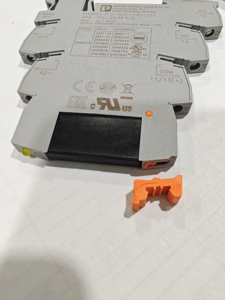
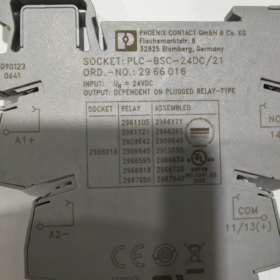
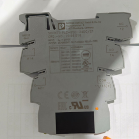
- Modello completo: PLC-BSC-24DC/21
- Numero d'ordine: 2966016
- Serie di marca: Contatto della Fenice PLC-INTERFACE ultra-slim relay base
- Ripartizione del modello
PLC: Base for PLC interface relay module
BSC: Basic economical base with screw connection
24DC: Rated control coil voltage DC24V
21: 1 contatto di scambio (1NO + 1NC, 1PDT single-pole double-throw)
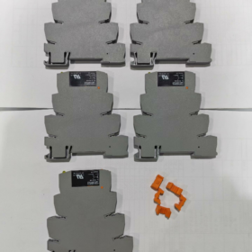
- Product Description: Base only, relay insert not included. Must be used with matching pluggable relays (2961105 / 2961118).
- Electrical Specifications of Control Side Input (A1+/A2-)
- Tensione di controllo nominale: 24 A DC
- Operating Voltage Range: 19.2 V DC ~ 30 A DC
- Built-in Protection Circuit: Freewheeling damping diode + reverse polarity protection diode to prevent PLC output burnout from reverse connection
- Status Indicator: Integrated yellow LED on base, lights steadily when coil is energized
- Input Power Consumption: ca. 1.1 W
- Minimum Driving Current: 5 mA, directly compatible with PLC NPN/PNP transistor outputs (S7-1200/1500, Mitsubishi, Innovazione, ecc.)
- Rated Parameters of Load-side Contacts (12/11 Comune, 14 Normalmente aperto, 12 Normalmente chiuso)
3.1 General Load Ratings
Maximum Switching Voltage: 250 V e / 30 A DC
Rated Continuous Thermal Current Ith: 6 UN
AC-15 Inductive Load (Contactor Coils): 6 UN / 250 V e
DC-13 Inductive Load (Elettrovalvole): 3 UN / 24 A DC
3.2 Isolamento & Withstand Voltage
Isolation Withstand Voltage (Coil to Contacts): 4 kV AC for 1 minuto
Withstand Voltage across Open Contacts: 2 kV CA
Resistenza di isolamento (DC 500 V Test): ≥10⁹ Ω
3.3 Resistenza elettrica (with Original Phoenix Relay Insert)
6 UN / 250 V e: 100,000 operazioni
3 UN / 24 A DC: 200,000 operazioni
3.4 Modulo di contatto: 1PDT Single-Pole Double-Throw (11 Comune, 14 NO, 12 NC)
- Mechanical Dimensions & Montaggio
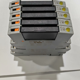
- Larghezza: 6.2 mm (ultra-slim design saves DIN rail space, zero-gap side-by-side mounting supported)
- Dimensioni complessive: W6.2 mm × H94 mm × D80 mm
- Guida di montaggio: Standard DIN NS35/7.5 rail
- Housing Flame Retardancy: UL94 V0
- Colore: Base body grey-green, relay latch orange
- Peso: ca. 45 G
- Specifiche del terminale (All M3 Screw Terminals)
- Fili applicabili:
Solid single-core wire: 0.14~2.5 mm²
Stranded multi-core wire: 0.14~2.5 mm²; massimo. 2.5 mm² with ferrule terminals
AWG Range: 26 AWG ~ 14 AWG
- Screw Torque: 0.6~0.8 N·m
- Wire Stripping Length: 8 mm
- Terminal Partition
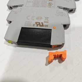
Left Side: Control circuit A1+, A2(connect to PLC outputs)
Right Side: Load circuit 12(NC), 11(COM), 14(NO)
- Condizioni ambientali & Approvazioni
- Temperatura operativa: -25 ℃ ~ +60 ℃
- Magazzinaggio & Transport Temperature: -40 ℃ ~ +85 ℃
- Grado di inquinamento: 3, for indoor industrial control cabinet installation
- Certificazioni: CE, cULus, VDE, GL Marine Approval, RoHS Compliant
- EMC Class: Class A industrial equipment
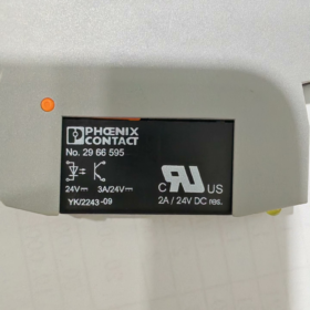
- Matching Relay Inserts (Must Be Ordered Separately)
| Relay Insert Model | Tensione della bobina | Capacità di contatto | Compatible Base |
| 2961105 | DC 24 V | 6 A 1PDT | 2966016 |
| 2961118 | DC 24 V with LED indicator | 6 A 1PDT | 2966016 |
- Scenari applicativi tipici
- PLC digital output isolation to drive small contactors, solenoid valves and indicator lights
- IO signal transfer and separation of strong/weak current on automated production lines
- On-off control of small loads for machine tools, packaging equipment and assembly lines
- Ultra-slim modular signal expansion for high-density IO cabinets
- Series Model Selection Comparison
| Modello | Ordine n. | Larghezza | Number of Contact Sets | Tensione della bobina |
| PLC-BSC-24DC/21 | 2966016 | 6.2 mm | 1 changeover | DC 24 V |
| PLC-BSC-24DC/21-21 | 2967015 | 14 mm | 2 changeover | DC 24 V |
| PLC-BSC-230UC/21 | 2966029 | 6.2 mm | 1 changeover | CA/CC 230 V |
- Brief Wiring Logic
- Connect 24 V DC PLC output to base terminals A1(+) and A2(-); LED illuminates and relay pulls in.
- Pull-in State: 11(COM) ↔ 14(NO) Chiuso; 11 disconnected from 12(NC).
- De-energized State: 11(COM) ↔ 12(NC) Chiuso; 11 disconnected from 14(NO).
- Load Circuit: Connect AC220 V / DC24 V loads to COM+NO or COM+NC for switching control.
- Troubleshooting Guidelines
- LED off: No PLC output, reversed A1/A2 wiring, loose terminals
- LED on but load inactive: Damaged relay insert, loose contact wiring, open-circuit load
- Frequent contact ablation: La corrente di carico supera 6 UN; external auxiliary contactor required for capacity expansion
- Unintended operation: No absorption component for inductive PLC loads; freewheeling diode can be paralleled on the base side
Application Scenarios of PHOENIX CONTACT PLC-BSC-24DC/21 (2966016)
Questo 6.2 mm ultra-slim PLC interface relay base mainly realizes PLC transistor output isolation & transfer, strong/weak current separation and small load switching for compact control cabinet wiring. It fits all 24 V DC PLC digital output applications, categorized into industry segments, equipment types and cabinet internal functions as below:
- General Automation OEM Equipment Applications
1.1 Macchine utensili & Metal Processing Equipment
CNC lathes, centri di lavoro, smerigliatrici, punch presses: PLC outputs drive cooling solenoid valves, lubrication pumps, tool magazine cylinders, indicator lights and small contactor coils
Bending machines, macchine da taglio: Control pneumatic clamps, safety door warning lights and alarm buzzers
Vantaggi: Ultra-slim to save cabinet space; pluggable relay allows fast replacement without wire disconnection during machine breakdowns
1.2 Confezione, Riempimento & Food Processing Machinery
Beverage filling machines, etichettatrici, flow wrapping machines, ordinamento & rejection equipment
Control material distributing cylinders, photoelectric rejection valves, conveyor start/stop, fault warning lights and hot air blowers
Suitable for clean-room control cabinets; screw terminals resist vibration and maintain stable service life under frequent switching cycles
1.3 3C Electronics, Lithium Battery & PV Equipment
Macchine per il posizionamento SMT, distributori, lithium battery filling/sealing equipment, PV module production lines
Drive micro solenoid valves, vacuum generators, sensor indicator lights and small signal contactors
High-density PLC output points fit the 6.2 mm narrow design for compact arrangement to solve space shortage in IO cabinets
1.4 Trasmettere & Logistics Equipment
Trasportatori a nastro, linee a rulli, automated warehouses, sorting lines, control cabinets matched with AGVs
Control track switch cylinders, stopper cylinders, position indicator lights, audio-visual fault alarms and guard lock prompts
- Discrete Manufacturing Production Line Applications
- Automotive Assembly Lines
Saldatura, coating and final assembly stations: Solenoid valves for robot clamps, station indicator lights, safety bypass prompts and pneumatic clamping mechanisms. Isolates heavy interference from welding machines to protect PLC output points from breakdown induced by inductive loads.
- Gomma & Plastic Molding Equipment
Macchine per stampaggio ad iniezione, estrusori: Barrel cooling fans, material suction solenoid valves, mold temperature controller signal switching and safety door status indicator lights
- Stampa & Macchinari tessili
Printing presses, warp knitting machines, stampa & attrezzature per la tintura: Tension cylinders, ink valves, shutdown alarms and fabric deviation correction actuators
- Municipal, Trattamento delle acque & HVAC Integrated Control Cabinets
- Impianti di trattamento delle acque reflue, water supply pump station control cabinets: Bar screen alarms, electric valve signals, liquid level indicator lights and auxiliary control of submersible pumps
- Aria condizionata centralizzata & air purification units: Air damper actuators, humidifier solenoid valves and differential pressure alarm lights
- Building intelligent control: Lighting zoning control, ventilatori di scarico, access status feedback and fire linkage signal transfer
Caratteristiche: Designed for 24/7 continuous operation; built-in freewheeling diode suppresses solenoid valve surge voltage to protect PLC I/O cards
- Nuova energia, Energy Storage & Test Equipment
- Control cabinets matched with PCS energy storage converters, lithium battery testing equipment and auxiliary cabinets of PV inverters
- High/low voltage electrical test benches and aging test equipment: Signal switching for test points, indicator lights and micro solenoid valves
Ampio intervallo di temperature operative (-25 ℃ ~ +60 ℃) fits indoor machine rooms and constant-temperature outdoor control cabinets
- Transito ferroviario & Small Construction Machinery Matching
Metro platform screen door control cabinets, electrical boxes for small construction machinery (loaders, macchine da taglio)
Drive warning lights, electromagnetic directional valves and operation panel indicator lights; vibration-resistant screw terminals prevent loose wiring
- Typical Internal Cabinet Functional Applications (General Retrofit & Project Matching)
- PLC Output Isolation Protection (Funzione fondamentale)
24 V transistor PLCs including Siemens S7-1200/1500, Allen-Bradley, Mitsubishi, Inovance and Xinje only supply 0.5 A output current, insufficient to directly drive solenoid valves or contactors. This relay expands the switching capacity to 6 A and isolates back EMF from inductive loads to avoid I/O point burnout.
- Physical Separation of Strong & Weak Current Signals
4 kV insulation isolation between 24 V weak-current PLC control circuits and 220 V AC load circuits prevents high voltage back-feed to controllers and improves equipment safety rating.
- High-Density IO Cabinet Wiring
6.2 mm ultra-slim width supports zero-gap side-by-side installation, doubling the number of relays on the same DIN rail length, ideal for centralized cabinets with massive I/O points.
- Signal Distribution & Contact Conversion
1 set of changeover contacts (1NA+1NC) enables one PLC signal to control two different loads simultaneously; NC contact can be used for fault alarm circuits.
- Rettifica dell'attrezzatura & Old Cabinet Capacity Expansion
Replaces standard 14 mm wide relay bases to save rail space when existing cabinet space is limited. Pluggable relay design allows on-site maintenance without wire disconnection and reduces downtime.
- Not Recommended Application Scenarios (Application Limitations)
- Circuiti di sicurezza, emergency stop and safety door interlocks (440R series safety relays are required; this product has no force-guided contacts and fails to meet PL e safety certification)
- High-power loads (single channel exceeding 6 A AC-15 / 3 A DC-13; external high-capacity contactors required for capacity expansion)
- Outdoor unenclosed enclosures (Grado di protezione IP20; must be installed inside standard sealed control cabinets)
- Unshielded cabinets with heavy interference from high-frequency high-voltage large inverters (surge suppressors must be added for matching use)
Complete Mounting Instructions for PHOENIX CONTACT PLC-BSC-24DC/21 (2966016)
- Basic Mounting Type: Standard DIN Rail Snap-in Installation (Only Official Mounting Method)
- Applicable Rail Specification
Only compatible with national/European standard NS 35/7.5 DIN mounting rail (35 larghezza mm, 7.5 mm height). Direct panel mounting via drilled holes or wall screw mounting is not supported.
- Arrangement Characteristics
Zero-gap dense side-by-side mounting available; IL 6.2 mm slim design requires no reserved heat dissipation gap for high-density IO cabinet layout. Install PLC-ATP insulating partitions between adjacent modules with mixed high/low voltage circuits for reinforced electrical isolation.
- Unrestricted Mounting Orientation
Can be mounted horizontally, laterally or vertically with no mandatory angle; only ensure adequate ventilation inside the control cabinet.
- Step-by-Step Rail Assembly & Disassembly
2.1 Base Installation Steps
- Remove oil stains and metal debris from the DIN rail surface and fix the rail firmly to the cabinet mounting plate.
- Hook the upper rear latch of the base onto the top edge of the DIN rail slot.
- Press down the lower half of the base until an audible click confirms the spring latch locks the base fully against the rail.
- Install multiple modules side by side seamlessly in sequence.
- Fit end stoppers at both rail ends if positioning is required to prevent sliding caused by vibration.
2.2 Base Removal Steps
- Cut off power and disconnect all wiring.
- Insert a flathead screwdriver into the spring latch slot at the bottom of the base.
- Pry downwards to release the lower locking mechanism.
- Tilt the bottom edge outward and lift the base up to disengage from the upper rail edge for removal.
- Relay Insert Plug-in Installation (Base Matching Operation)
This product is base-only and must be paired with 2961105 / 2961118 relay inserts:
- Align the relay with the upper slot of the base and press straight down for insertion.
- The orange latch automatically locks to prevent loosening under vibration.
- Removal: Pinch the orange latch to flip outward, then pull the relay insert upward for quick replacement without disconnecting wires.
- Terminal Wiring Installation (M3 Screw Connection)
- Standard wire stripping length: Fixed at 8 mm; excessive length risks short circuits, insufficient length causes poor contact.
- Applicable Cables: 0.14~2.5 mm² solid/stranded wires, AWG26~14; ferrule terminals are recommended for stranded wires.
- Coppia di serraggio: 0.6~0.8 N·m; excessive torque strips screws, insufficient torque leads to heat and poor contact.
- Terminal Partition: Left side A1/A2 (Circuito di controllo PLC); Right side 11/12/14 (load contact circuit). Clear zoning facilitates wiring.
- Optional Matching Mounting Accessories
- PLC-ATP Insulating Partition: Install between adjacent modules where one side carries 220 V high voltage and the other carries 24 V low voltage to strengthen electrical isolation.
- FBST Plug-in Bridge Connectors: Condividere 24 V power supply for multiple modules to parallel A1/A2 terminals in batches and reduce redundant wiring.
- DIN Rail End Stoppers: Secure both ends of a full row of modules to prevent sliding and dropping during equipment transportation and vibration.
- Mounting Environment & Restrictions
- Grado di protezione IP20; only for installation inside sealed control cabinets. Outdoor and unenclosed box installation prohibited.
- Operating ambient temperature: -25 ℃ ~ +60 ℃; reserve ≥10 mm clearance above modules for heat dissipation.
- Keep away from heat-intensive and high-interference devices such as inverters and contactors; avoid tight fitting with high-power heat sources.
- Do not install in areas with direct exposure to water mist, heavy dust or corrosive gas.
- Mounting Prohibitions
- Violent knocking of base or relay insert is forbidden to avoid rear latch fracture.
- Do not pull the base diagonally with force to prevent rail deformation and latch damage.
- High/low voltage modules cannot be placed closely without insulating partitions, which carries risk of dielectric breakdown and electric leakage.
- Exposed loose copper strands from multi-core wires at terminals are prohibited to avoid phase-to-phase short circuits.


 Relè di sicurezza")


")
NH42-63-318x560.png "Commutatori automatici di tipo PC CHINT (ATS)NH42-63/4SZ")


