 コンタクタ,サーキットブレーカー,ソーラーインバーター,電気メーター,太陽電池

2つのモデルは、 物理的に設置互換性がある, ただし、電源の種類と機能構成には重大な違いがあります。. システム要件に応じて調整が行われます: セルフパワー設計の電圧範囲を確認する; 通信機能も完全互換; 表示性能と測定精度が向上. 主な制限は、補助電源がサポートされていないことです。.
- モデルセグメント定義の詳細な比較
| モデル | セグメント | 意味 | 主な違い |
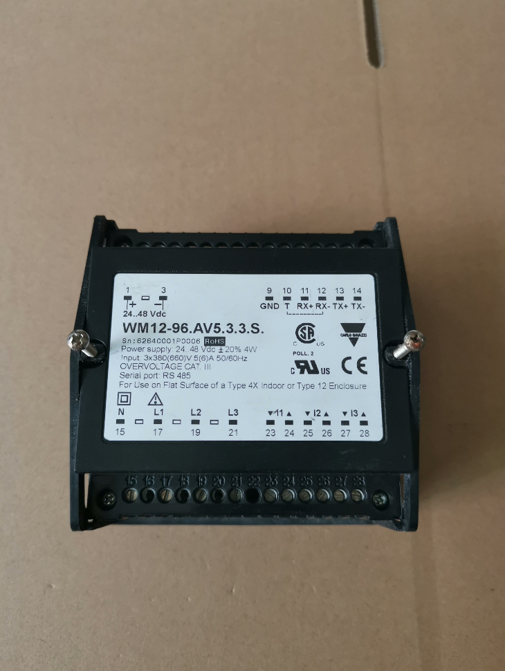
| WM12-96.AV5.3.3.S | WM12-96 | 96×96mm パネル取付型キーパッド内蔵三相指示計 | 旧シリーズ, LEDディスプレイ, 補助電源設計 |
| AV5 | 測定範囲: 380/660V L-L / 5(6)そしてAC | 同じ測定範囲 | |
| 3 | 3-不平衡負荷用の位相システム | 同じシステムタイプ | |
| 3 | 18–60VDC補助電源 | DC補助電源 | |
| S | RS485通信あり | 同様の通信機能 | |
| WM1596AV53XoSX | WM1596 | 96×96mmパネル取付型三相電力アナライザ | 新シリーズ, 液晶ディスプレイ, 自己電源設計 |
| AV5 | 測定範囲: 380/660V L-L / 5(6)そしてAC | 同じ測定範囲 | |
| 3 | 3-不平衡負荷用の位相システム | 同じシステムタイプ | |
| ソ | セルフパワー (補助電源は不要です) | 外部電源は不要です | |
| S | RS485通信あり | 同様の通信機能 | |
| × | 脈なし / 警報出力 | 追加の出力関数はありません |
- コアパラメータの互換性の比較
| パラメータのカテゴリ | WM12-96AV5.3.3.S | WM1596AV53XoSX | 互換性 | 備考 |
| 物理的な設置 | 96×96mmパネル, 切り抜き92×92mm | 96×96mmパネル, 切り抜き92×92mm | ✅ 完全な互換性 | 直接交換可能な取り付け, パネルの変更は不要です |
| 表示タイプ | 3×3桁LED, 14mm桁高さ | 視認性を高めたグラフィックLCD | ✅ 機能アップグレード | 表示内容の充実, 中国語インターフェースをサポート |
| 測定精度 | 電圧/電流: ±0.5%FS | 電圧/電流: ±0.5% GDR | ✅ 精度の向上 | より高度な計測要件を満たします |
| 力: ±(1% FS + 1 桁) | アクティブエネルギー: クラス 1 | |||
| 電源の種類 | 18-60VDC 補助電源 | セルフパワー (120–240V L-N / 208–415V L-L) | ❌ 互換性がありません | 外部電源は不要です, ただし、システム電圧は範囲内である必要があります |
| コミュニケーション | RS485, Modbus RTU, 9600bps | RS485, Modbus RTU, 9600/19200bps | ✅ 互換性あり | マッチング用に設定可能な通信パラメータ |
| 測定機能 | 基本的な電気パラメータ, 最大値表示 | 基本パラメータ + 電圧/電流THD, 双方向エネルギー測定 | ✅ 機能拡張 | 包括的なモニタリングのための高調波解析の追加 |
| 侵入保護 | フロントIP65, 端子IP20 | フロントIP51, 端子IP20 | ⚠️若干減りました | 屋内での使用には影響ありません; 屋外/粉塵の多い環境では追加の保護が必要 |
| 動作温度 | -10℃~+50℃ | -10℃~+50℃ | ✅ 完全な互換性 | 一貫した環境適応性 |
- 代替実現可能性マトリックス
3.1 ✅ 直接交換に該当するシナリオ
システム電圧は自己給電範囲に一致します (120–240V L-N / 208–415V L-L) 外部補助電源は不要です
高調波解析や高度なエネルギー計測機能が必要
ディスプレイの可読性が高い方が好ましい (LEDの代わりにLCD)
WM15シリーズの機能を最大限に活かした新プロジェクト設計
3.2 ⚠️必要な調整を行った上で交換
| システム状態 | 調整措置 | 注意事項 |
| 18~60VDC補助電源を装備したオリジナルシステム | 電源は接続せずに配線しておいてください, またはコストを節約するために削除します | WM15 セルフパワーバージョンは外部補助電源を必要としません |
| システム電圧が自己給電範囲を超えています | 補助電源付きの WM15 バージョンを選択してください (例えば. WM1596AV53AoSX) | 補助電源モデルは 208 ~ 600V L-L をサポート |
| 脈 / アラーム出力が必要です | 出力付きモデルへの置き換え (例えば. WM1596AV53XoSO) | “○” = 1 リレー出力; “それで” = 2 リレー出力 |
3.3 ❌ 置き換え不可能なシナリオ
| 制限事項の説明 |
| システム電圧が 120V L-N 未満で、利用可能な補助電源がない |
| DC補助電源は必須です (例えば. 安全規格の要件) |
| フロントパネルの保護等級はIP65が義務付けられています (例えば. 屋外または粉塵の多い環境) |
| 予算は限られており、基本的な表示機能のみが必要です (WM15はWM12より価格が高い) |
- 交換実装ガイドライン
4.1 ハードウェアのインストール手順
- システムの電源を切ります, 元のWM12ユニットを取り外します, CTと電圧の配線をそのままにします.
- WM1596AV53XoSXを既存の96×96mmパネルカットアウトに直接取り付けます。.
- CTを接続する (現在) 同じ端子定義に従った電圧入力ワイヤ.
- 純正のDC補助電源を接続しないでください。 (WM15はセルフパワーです).
- リモート監視が必要な場合は、RS485 通信ケーブルを配線します。.
4.2 主要な構成設定
| 構成アイテム | パスの設定 | 推奨値 |
| 通信パラメータ | メニュー → 設定 → 通信 | 住所: 1–247, ボーレート: 9600bps, 8N1 |
| システムタイプ | メニュー → 設定 → システム → 配線 | 3P4W (3-相4線式) または3P3W (3-相3線式) |
| 表示モード | メニュー → 設定 → 表示 | 電圧の周期表示, 現在, 力, 頻度 |
| 高調波測定 | メニュー → 設定 → 測定 → THD | 有効にする (デフォルトでアクティブ化) |
4.3 公式の交換推奨事項
カルロ・ガヴァッツィは、WM15 シリーズを WM12 シリーズの最終後継モデルと正式に定義, 特集:
より高い測定精度 (クラス 1 活性エネルギー)
充実した機能: 高調波解析, 双方向エネルギー計測
より長い製品ライフサイクルと技術サポート
UCS設定ソフトウェアと互換性があり、一括パラメータ設定が可能
- 交換決定ガイド
- システム電圧は 120 ~ 240V L-N の範囲内ですか / 208–415V L-L?
はい: WM1596AV53XoSXは直接使用可能
いいえ: 補助電源付きの WM15 モデルを選択してください (例えば. WM1596AV53AoSX)
- RS485通信は必要ですか?
はい: 末尾にSが付いているモデルを選択してください
いいえ: Sなしのモデルを選択してください (例えば. WM1596AV53XoXX)
- 脈あり / アラーム出力が必要です?
はい: 末尾にOが付いているモデルを選択してください (例えば. WM1596AV53XoSO)
いいえ: 選択した元のモデルを保持する

