 접촉기,회로 차단기,감지기,인코더,PLC,변환기


기본정보
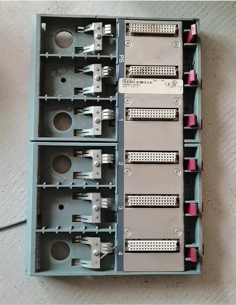
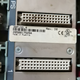
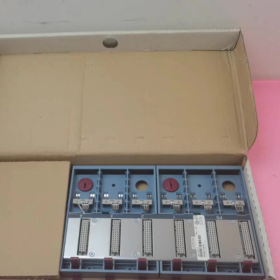
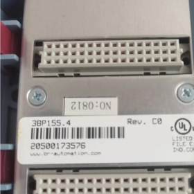
모델: 3BP155.4
제품군: 비&R 시스템 2005 (레거시 2005 시리즈 PCC, 더 이상 사용되지 않음)
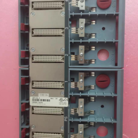
유형: 6-슬롯 패시브 백플레인 / 랙 백플레인
변형 차별화
✅ 3BP155.4: 6 슬롯, 백업 배터리함 없음
✅ 3BP155.41: 6 슬롯, 백업 배터리 장착부 포함 (배터리 부품 번호: 0AC201.9)
슬롯 정의: 슬롯 1 전원 모듈 전용 (3PSxxx); 나머지 5 슬롯은 CPU를 지원합니다, I/O 및 통신 모듈.
- 주요 전기 & 기계 사양
| 목 | 매개변수 |
| 슬롯 수 | 6 슬롯 (1 PS 슬롯 + 5 모듈 슬롯) |
| 전체 치수 | 240 mm (여) × 165 mm (시간) × 23 mm (디) |
| 보호 등급 | IP20 (캐비닛 설치 전용) |
| 작동 온도 | 0 ℃ ~ +60 ℃ |
| 보관온도 | -25 ℃ ~ +70 ℃ |
| 상대습도 | 5~95%RH, 비응축 |
| 인증 | CE, UL/cULus, EAC, UKCA |
| 설치 | DIN 레일 장착 |
| 재료 | 금속 차폐 백플레인 + 플라스틱 하우징 |
- 체계 2005 전체 범위 백플레인 비교표
| 모델 | 슬롯 수 | 배터리실 |
| 3BP150.4 / 3BP150.41 | 15 슬롯 | .41 버전 장착 |
| 3BP151.4 / 3BP151.41 | 12 슬롯 | .41 버전 장착 |
| 3BP152.4 / 3BP152.41 | 9 슬롯 | .41 버전 장착 |
| 3BP155.4 / 3BP155.41 | 6 슬롯 | .41 버전 장착 |
- 호환성 지침
- 지원되는 모듈: 모든 시스템 2005 시리즈 모듈 (3PS 전원 공급 장치, 3CP CPU, 3DM/3DO/3AI/3AO I/O 모듈, 3EX 통신 모듈)
- 비호환성: X20 시리즈 모듈과 혼합할 수 없습니다. (물리적 커넥터와 백플레인 버스가 호환되지 않습니다.)
- 노후화된 장치를 위한 교체 솔루션
유지보수 예비 부품: 새로운 잉여분 소싱 또는 3BP155.4 사용 / 3BP155.41
새로운 프로젝트 업그레이드: B로 전체 마이그레이션&R X20 시스템 (직접적인 드롭인 백플레인 교체 없음; 하드웨어 및 프로그램 수정 필요)
- 운영 지침 & 현장 함정 회피
- 최소 예약 20 방열을 위한 DIN 레일 양쪽 끝의 mm 간격;
- 이것은 패시브 백플레인입니다.. 전원 공급은 슬롯에 설치된 전원 모듈에서 전적으로 제공됩니다. 1;
- 3BP155.4에는 백업 배터리를 장착할 수 없습니다.. 정전 시 SRAM 프로그램/데이터 보존이 필요한 경우, 3BP155.41을 선택하세요.;
- 다른 시리즈의 백플레인을 접합하거나 확장하지 마십시오.. 체계 2005 백플레인은 다중 랙 계단식 연결을 지원하지 않습니다.;
- 백플레인 커넥터 핀의 손상을 방지하려면 모듈을 제거하기 전에 항상 전원을 끄십시오..
- 일반적인 표준 구성 예
슬롯 1: 3PS465.9 (전원공급장치)
슬롯 2: 3CP153.9 (CPU)
슬롯 3~6: 디지털 I/O, 아날로그 입출력, Profibus 또는 CANopen 통신 모듈
요청 시 추가 제공 가능:
백플레인 핀아웃 정의;
중고품의 간단한 검사 절차;
시스템에서 마이그레이션 계획 완료 2005 X20으로.
B에 대한 문제 해결 절차 완료&R 3BP155.4 패시브 백플레인
메모: 3BP155.4는 통합 칩이나 능동 회로가 없는 수동 백플레인입니다.. PCB 트레이스만 포함되어 있습니다., 백플레인 커넥터 및 DIN 레일 접지 경로. 일반적인 고장에는 구부러지거나 산화된 핀이 포함됩니다., 깨진 구리 흔적, 납땜 불량, 접지 불량 및 커넥터 단락.
모델별: 3BP155.4 (배터리 하우징 없음) ≠ 3BP155.41 (배터리 하우징 포함). 기계적으로 상호 교환 가능, 동일한 백플레인 회로 레이아웃.
- 일반적인 실패 증상 (백플레인 오류와 모듈 오류 구별)
의심스러운 백플레인 오류 증상
- 모든 모듈이 특정 슬롯에 삽입되면 오류가 발생합니다., 동일한 모듈이 다른 슬롯에서는 정상적으로 작동하는 동안
- 여러 인접 슬롯에 동시 통신 오류가 발생함 (깨진 백플레인 버스 흔적)
- 간헐적인 모듈 드롭오프, 산발적인 모듈 인식 손실; 캐비닛을 두드리거나 흔들 때 오류 재현 가능
- 전원 공급 장치 슬롯이 정상적으로 작동합니다., 하지만 특정 슬롯에는 백플레인 버스 전원이 없습니다.
- 빈번한 핫스왑 경보, 통신 CRC 오류, PCC 부팅에서 누락된 모듈을 보고함
- 한 슬롯에 모듈을 삽입하면 전원 트립이 발생함 / 단락 (단락된 백플레인 핀)
백플레인으로 인해 발생하지 않은 오류
모든 슬롯에서 단일 모듈이 실패함 → 모듈 결함
모든 슬롯에서 모듈이 감지되지 않음 → 3PS 전원 공급 장치 및 3CP CPU 우선 검사
모든 하드웨어 모듈이 정상적으로 작동합니다., 프로그램 오류만 발생 → 소프트웨어 또는 매개변수 구성 문제
단계 1: 육안검사 (전원을 분리해야 합니다.)
- 모든 모듈을 제거하고 모든 슬롯의 스프링 접점을 검사합니다.
굽은, 기울어지거나 브리지된 핀 = 단락 위험, 백플레인이 비난됨
검게 변한, 산화된, 녹청이 있는 부식된 핀 → 접촉 불량
- PCB 뒷면 검사: 탄 자국이 있는지 확인하세요, 균열 (패시브 백플레인에 커패시터 없음. 탄 흔적이 보이면 즉시 폐기하세요.)
- DIN 레일용 접지 스프링 클립을 확인하세요.: 변형되거나 누락된 접지 클립으로 인해 EMC 간섭 및 무작위 통신 오류 발생
경고:커넥터 스프링 핀을 무리하게 구부리지 마십시오., 내부 PCB 트레이스 파손을 쉽게 유발합니다..
단계 2: 멀티미터 연속성 테스트 (코어 검사 방법)
테스트 전제 조건
장치 전원을 완전히 끄고 외부 전원을 분리합니다.; 모든 모듈 제거.
멀티미터를 연속 경고음 모드로 설정 / 저항 모드.
체계 2005 백플레인 버스는 다음으로 구성됩니다.: 파워 레일 (+5다섯, 접지), 병렬 주소 버스, 데이터 버스와 클럭 라인
필수 테스트 항목
- 공통 GND 라인
모든 슬롯의 GND 핀은 상호 전도성이어야 합니다.;
GND는 백플레인 금속 하우징으로 전도되어야 합니다. / DIN 레일 접지 클립.
✘ 이상: 슬롯의 GND 연결 끊김 → PCB 접지 트레이스 파손.
- 백플레인 +5V 전원 레일
+5모든 슬롯의 V 핀은 상호 전도성이어야 합니다.;
⚠ 심각한 경고: +5V와 GND 간의 연속성 = 내부 백플레인 단락. 백플레인을 폐기해야 합니다..
- 버스 신호 라인의 슬롯 간 연속성
체계 2005 데이지 체인 병렬 백플레인 버스 채택. 인접한 슬롯 사이의 신호 라인은 전도되어야 합니다.:
슬롯 2 ⇔ 슬롯 3 신호 라인 전도성
슬롯 3 ⇔ 슬롯 4 신호 라인 전도성
슬롯 4 ⇔ 슬롯 5 신호 라인 전도성
슬롯 5 ⇔ 슬롯 6 신호 라인 전도성
✘ 이상: 인접한 슬롯 사이의 개방 회로 → 내부 PCB 버스 트레이스 파손.
빠른 교차 테스트 방법 (현장 응급진단, 핀아웃이 필요하지 않습니다)
모듈 교환 테스트 (현장 자동화 엔지니어가 가장 일반적으로 채택하는)
작업 단계:
- 전원 공급 장치와 CPU를 슬롯에 고정해 두세요.;
- 정상으로 확인된 I/O 모듈을 순차적으로 슬롯에 삽입 2,3,4,5,6;
- 전원을 켜고 PCC가 모듈을 인식하는지 확인하세요.:
한 슬롯만 모듈 감지 실패 → 해당 슬롯에 대한 커넥터 또는 트레이스가 손상됨
Slot2는 정상적으로 작동합니다., 슬롯3이 감지되지 않음, Slot3 이후의 모든 슬롯이 실패 → Slot2와 Slot3 사이의 버스 추적이 끊어짐 (일반적인 내부 백플레인 손상)
3단계: 전동 기능 테스트 (전제 조건: 눈에 보이는 단락 손상 없음)
구성: 3PS 전원 공급 장치가 작동하는 슬롯 1, 3CP CPU가 작동하는 슬롯2, 남은 슬롯은 비어있습니다.
- 전원 켜기. 하드웨어 알람 없이 컨트롤러가 부팅되는 경우 → 기본 백플레인 전원 레일은 기본적으로 손상되지 않습니다.
- 검증된 양품 모듈을 하나씩 삽입, Automation Studio 내부의 하드웨어 진단 확인
진단 메시지: Slotx 모듈 누락 / 버스 오류
고정 슬롯에 대해 알람이 지속됩니다., 모듈 대신 슬롯에 오류가 발생함 → 백플레인 오류가 확인됨
- 수리가 불가능한 세 가지 시나리오 – 직접 교체 필요
- +5V와 GND 사이의 내부 단락 (멀티미터 연속성 테스트를 통해 확인됨)
- 깨진 PCB 기판 또는 깨진 내부 버스 트레이스 (크로스 슬롯 신호 라인 사이의 개방 회로)
- 심하게 변형된 스프링 접점, 브릿지 핀, 녹은 커넥터 플라스틱
- 일반적인 오해
- ❌ 오해: “패시브 백플레인은 실패할 수 없습니다.”. 대략적인 모듈 삽입, 운송 진동 및 장기간의 고온으로 인해 내부 PCB 트레이스가 파손되거나 납땜 접합 불량이 발생할 수 있습니다..
- ❌ 가벼운 산화는 알코올 세척으로 항상 고칠 수는 없습니다.: 피로한 스프링 접점은 간헐적인 고장을 일으키는 경향이 있습니다.; 교체를 권장합니다.
- ❌ 설명: 3BP155.4는 백플레인일 뿐입니다.. CPU 부팅 실패는 결함이 있는 백플레인과 동일하지 않습니다.. 항상 3PS 전원 공급 장치와 3CP CPU를 먼저 확인하십시오..
- 생산 복구를 위한 긴급 임시 솔루션
하나의 슬롯에만 손상된 흔적이 있는 경우:
결함이 있는 슬롯을 사용하지 마십시오., 임시 작동을 위해 모듈을 나머지 기능 슬롯으로 재배치.
장기적인 솔루션: 3BP155.4 예비 부품 교체, 또는 X20 플랫폼으로의 전체 마이그레이션을 평가해 보세요..
요청 시 이용 가능한 지원 자료:
- 정밀한 멀티미터 측정을 위한 3BP155.4 슬롯 커넥터의 전체 핀아웃 정의;
- Automation Studio에서 System2005 백플레인 버스 오류를 보기 위한 탐색 경로.





NH42-63-318x560.png "CHINT PC형 자동절환스위치 (ATS)NH42-63/4SZ")



