 접촉기,회로 차단기,감지기,인코더,PLC,변환기

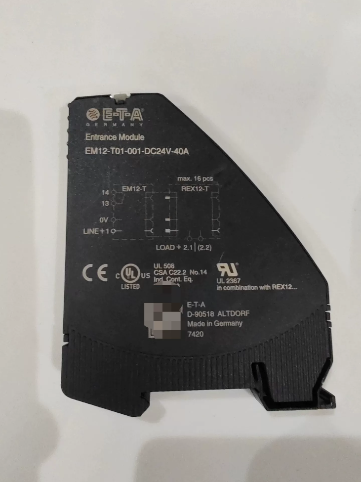

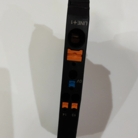

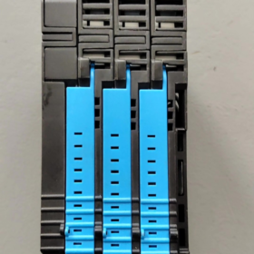
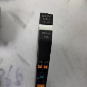
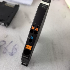
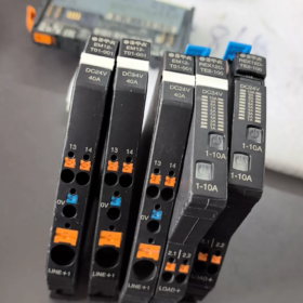
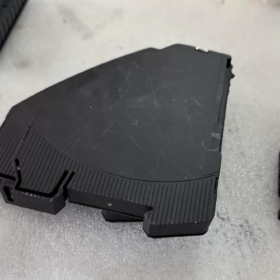
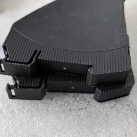
(완전한 모델: EM12-T01-001-DC24V-40A)
- 기본정보
상표: E-T-A Germany
시리즈: REX12-T Modular DC Power Distribution System
제품명: Main Feed Module / Power Bus Distribution Module
애플리케이션: Main inlet unit for REX12-T electronic circuit protector system, which distributes DC24V positive bus power uniformly to a full row of multi-channel protectors
- 모델 코드 분석
`EM12-T01-001`
- EM12: Feed module series matched with REX12
- 티: Standard analog signal type (without IO-Link communication; equipped with passive collective alarm contact Si)
- 01: Single positive pole feed version
- 001: Basic hardware version with standard DC24V, 40A specifications
Full suffix specifications:
DC24V: 정격 작동 전압
40에이: Maximum total inlet current of the module
- 핵심 전기 매개변수
| 매개변수 항목 | 사양 값 |
| 정격전압 | DC24V, operating range DC18~30V |
| Max Total Inlet Current | 40에이 |
| No-Load Static Power Consumption | Typical 10mA |
| 역극성 보호 | Built-in anti-reverse diode |
| Voltage Drop Buffer | 10ms (no false alarm for short-term voltage drop) |
| Alarm Contact Si | Normally open passive contact; load DC30V/0.5A, minimum driving 10V/1mA |
| 배선 방법 | Tool-free push-in spring terminals, max 10mm² copper wire |
| 유전체 내전압 | Input/Output AC2000V for 1 분 |
| 절연저항 | ≥100MΩ @500VDC |
- 환경 & 기계적 치수
설치: 표준 35mm DIN 레일
전체 치수: W12.4mm × H98mm × D80mm
작동 온도: -25℃ ~ +60℃
Storage/Transport Temperature: -40℃ ~ +85℃
| 보호 등급 | IP20 (for cabinet internal use only) |
| 인증 | UL508A, CSA, CE, RoHS 규제, 도달하다 |
- 핵심 기능
- Central Bus Power Distribution
Connect external 24VDC power supply to this module. Built-in metal busbars on the side automatically supply power in parallel to all series-connected REX12-T circuit protectors on the right side of the rail without cross-module wiring.
- Global Collective Fault Alarm (Si Contact)
Once any REX12 protector trips due to overload or short circuit, the internal passive Si contact opens. It can be connected to PLC or indicator lights to realize unified fault signal for the entire row of circuits.
- 역극성 보호 & Voltage Fluctuation Resistance
Reversed positive and negative power poles will not damage the module. The 10ms voltage drop buffer prevents false alarms caused by instantaneous voltage drop of switching power supplies.
- Expansion Compatibility
Unlimited series connection of REX12 single/dual-channel electronic circuit breakers on the right side. Multiple EM12-T01 modules can be connected in parallel to expand total current capacity.
- 일반적인 애플리케이션 시나리오
24VDC load distribution in industrial control cabinets: PLC 출력, 서보 드라이브, 센서, 솔레노이드 밸브, 로봇, on-board DC power distribution for rail transit, electric control boxes for construction machinery.
- Comparison with Same Series Models
- EM12-T01-001: Standard analog type with only passive alarm contacts, 통신 기능 없음
- EM12D-T: Intelligent communication version supporting IO-Link/Modbus RTU, capable of reading channel current and fault codes
- EM12-T00: Simplified version without alarm contacts
- PM12-T: Potential expansion module for multi-row busbar extension
- Standard Full Order Name
완전한 주문 모델: EM12-T01-001-DC24V-40A
Reference Stock SKUs for Distributors: DigiKey 302-1471-ND, RS 175-0362
Complete Installation Specification for E-T-A EM12-T01-001-DC24V-40A
- Standard Mounting Form
Exclusive Standard Mounting: TH35-7.5 standard 35mm DIN rail (EN50022)
No base screw fixing or wall-mounted options; only DIN rail clip-on installation. Only horizontal side-by-side mounting is permitted; vertical, upside-down or tilted installation is prohibited.
전체 치수: W12.4mm × H98mm × D80mm, single module width, seamlessly connected side by side with REX12 circuit breakers of the same series.
- DIN Rail Clip-In Installation Steps (Power Off Operation Required!)
- Rail Preprocessing
Adopt standard steel/aluminum TH35 rail and deburr after cutting. Mount the rail horizontally with fixing screw spacing ≤250mm to avoid shaking and deformation.
- Module Clip-In
Hook the upper slot of the module onto the top edge of the DIN rail, press down the bottom of the module gently until a “딸깍 하는 소리” sound indicates full locking. Verify no vertical looseness and the module cannot be lifted upward.
- Core System Layout Rules
EM12-T01 must be installed at the far left start of the entire REX12 circuit as the main power inlet point;
Fit the side metal busbar on the right of the module against the left busbar of the next REX12 breaker, close the side connecting latch to realize parallel bus power supply;
A single EM12-T01 supports maximum 40 series-connected REX12 electronic circuit breakers;
Multi-circuit expansion: Multiple EM12-T01 modules shall supply power independently; direct side-by-side interconnection of multiple EM12 modules is forbidden.
- Dismantling Specification
Disconnect main power first. Use a flathead screwdriver to pry down the bottom latch and lift the module upward for removal. Disassembling series-connected modules under live power is strictly forbidden, which will cut off the busbar and cause circuit power failure.
- Wiring Installation (Compatible with Top/Bottom Cable Entry)
Terminal Zones & Wire Gauge Specifications
- LINE+ (24V main positive inlet, primary power supply)
Applicable wire: 0.5~10mm² multi-strand copper wire, M4 screw terminal, recommended torque 1.2N·m
- 0다섯 (Common DC negative terminal)
Applicable wire: 0.14~2.5mm²
- Si (Passive collective fault alarm contact)
Applicable wire: 0.14~2.5mm², max load DC30V/0.5A
배선 요구 사항
Both top and bottom cable entry are available; select wiring direction according to cabinet layout;
Heavy main inlet wires (≥6mm²) shall be routed separately from Si signal wires in different cable ducts to reduce interference;
Close the side interconnection latches of modules only after all wiring is completed, then switch on power.
- 열 방출 & Spacing Installation Requirements
- Reserve ≥50mm vertical ventilation gap between upper and lower components on the same DIN rail;
- This module is a 40A high-current feed unit; do not mount it close to heat-generating components such as high-power power supplies, inverters and contactors;
- No mandatory isolation gap for densely arranged multiple modules, but cabinet ambient temperature shall be controlled ≤60℃;
- Natural convection ventilation must be guaranteed inside the cabinet; install cooling fans for sealed cabinets without ventilation.
- Reinforced Installation for Vibration & 가혹한 근무 조건
For high-vibration scenarios including machine tools, rail transit and construction machinery:
- Install DIN rail end stops at both rail ends to prevent horizontal sliding of modules;
- Attach 3mm rubber shock-absorbing pads to the rail back to reduce resonance;
- Regularly recheck terminal torque and latch locking status.
- 엄격한 설치 금지
- 수직의, upside-down or over 45° tilted installation is forbidden, which deteriorates heat dissipation and triggers overheat protection;
- Live plugging, unplugging or disassembly of series-connected modules is forbidden; busbar power cut will cause equipment shutdown;
- Installing EM12 in the middle or right side of REX12 circuit is forbidden, leading to bus power supply failure;
- Inlet wires thinner than 0.5mm² or thicker than 10mm² are forbidden, resulting in loose terminal crimping and overheating;
- Direct installation without protection in dusty, water mist or condensation environments is forbidden (IP20 only for cabinet internal use);
- Long-term total load current of single EM12 shall never exceed 40A rated value.
- Recommended Auxiliary Installation Materials
- DIN rail end fixing stops (prevent module sliding);
- M4 torque screwdriver (unified terminal tightening torque 1.2N·m);
- Crimp terminals for multi-strand wires to avoid short circuit caused by scattered copper strands;
- Cable duct separation: Route 24V power main wires and Si alarm signal wires separately.
Temperature Parameters of E-T-A EM12-T01-001-DC24V-40A (Original Manufacturer Manual Standard)
- Normal Ambient Operating Temperature
Standard Operating Range: -30 ℃ ~ +60 ℃, condensation is strictly prohibited throughout operation (안에 60204-1 cabinet application standard)
23℃ ambient temperature: Continuous full-load operation at 40A is allowed
40℃: Derate rated current to 95% (38에이)
50℃: Derate rated current to 90% (36에이)
60℃: Derate rated current to 85% (34에이)
Dense side-by-side installation of multiple modules: Further derate current to 80% of the above value
- Altitude Temperature Derating (High-Altitude Working Conditions)
2000m 이하: Full support for -30~+60℃ operating range
3000중: Maximum allowable ambient temperature reduced to +55℃
4000중: Maximum allowable ambient temperature reduced to +50℃
- 저장 & 운송 온도 (Power-Off Status)
보관 온도: -40 ℃ ~ +70 ℃ (with original factory packaging)
Long-Term Storage Limit: -40℃ ~ +85℃ (short-term exposure only, no power-on allowed)
- 설치 & Wiring Ambient Temperature
Operating environment for assembly and wiring: +5 ℃ ~ +60 ℃. Terminal disassembly and assembly are not recommended below 5℃; cold wires tend to fray and lead to unstable terminal torque.
Supplementary Usage Limitations
- IP20 rating only applies to cabinet internal use; cannot be directly exposed to outdoor environments with extreme temperature, water mist or dust;
- For sealed cabinets without forced cooling fans, long-term cabinet ambient temperature is recommended to be controlled ≤50℃;
- No functional failure occurs when starting at -30℃ low temperature, but preheat under no-load condition for a period before full-load operation under cold state.





NH42-63-318x560.png "CHINT PC형 자동절환스위치 (ATS)NH42-63/4SZ")



