 접촉기,회로 차단기,태양광 인버터,전기 계량기,태양 전지

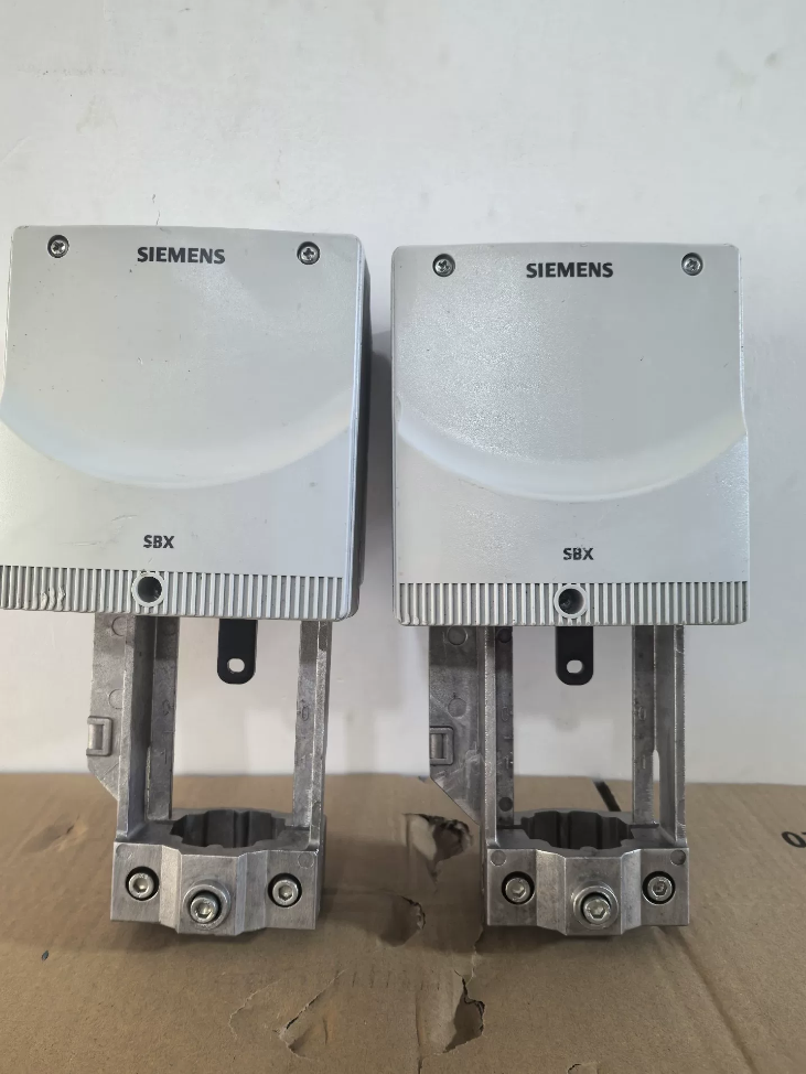

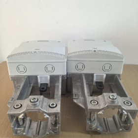
The SBX61 is a standard electric modulating valve actuator from 지멘스 Acvatix™ series under the Smart Infrastructure Building Automation product line. It is specially designed for 20mm-stroke 2-way/3-way globe valves. Powered by safe AC 24V supply, it supports DC 0…10V analog proportional control with factory-fitted full-range valve position feedback. It automatically returns to fully closed position upon loss of control signal. Featuring a snap-on direct mounting structure, it enables rapid installation without on-site commissioning. It is widely used for flow regulation in building automation systems including HVAC, district heating, cleanroom air conditioning and water treatment.
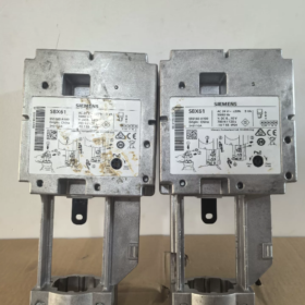
Per Siemens Acvatix series naming convention, each segment of the model code is explained as follows:
SB: 제품 시리즈 식별자, representing basic Acvatix electric globe valve actuators dedicated to driving building automation valves
엑스: Stroke specification code, standing for 20mm rated stroke (SBV models in the same series correspond to 40mm rated stroke)
61: Power supply and control type code, indicating AC 24V operating voltage, DC 0…10V analog positioning signal, built-in 0–10V position feedback, and automatic full-close return when control signal is lost
핵심 기술 사양
전기 등급
| 매개변수 항목 | 사양 | 비고 |
| Operating Power Supply | AC 24V ±20% | Compatible with 50/60Hz mains frequency |
| Rated Power Consumption | 5버지니아 (at 50Hz) | Low power consumption in holding state |
| Control Signal Input | DC 0…10V | Analog proportional control |
| Signal Input Impedance | >100 kΩ | Matches output of standard DDC controllers |
| Valve Position Feedback Output | DC 0…10V | Linear correspondence with valve opening |
| Feedback Load Capacity | Load impedance >10 kΩ | 맥스. 10 actuators can be connected in parallel |
| Fail-Safe Mode | Auto full-close on signal loss | Only active when control signal is disconnected while power supply remains intact |
Mechanical Performance Parameters
| 매개변수 항목 | 사양 | 비고 |
| Rated Stroke | 20mm | Full-stroke linear displacement |
| Rated Output Thrust | 800N | Continuous output thrust |
| Full-Stroke Travel Time | 120에스 | Constant-speed operation across full range |
| 수동 재정의 | Standard spanner-type manual adjustment | Manually open/close valve during power failure or commissioning |
| Valve Position Indication | Mechanical stroke scale | Intuitive real-time valve position display |
| 장착 유형 | Snap-on direct mounting | Tool-free installation, no adjustment required for matched valves |
물리적 & 환경 매개변수
인클로저 등급: IP40 (standard for indoor installation)
작동 주변 온도: -10℃ ~ +55℃
저장 & Transport Temperature: -40℃ ~ +70℃
상대습도: 5% ~ 95%, 비응축
장착 위치: Vertical indoor installation with valve stem pointing straight down
Allowable Medium Temperature (when assembled with valve): +1℃ ~ +95℃
HS코드: 85371090
Standard Built-in Functions & Factory Scope of Supply
Onboard Standard Functions
- Proportional Control: Precise positioning via 0–10V analog signal with linearity better than ±5%
- Valve Position Feedback: Native 0–10V position signal output for system position readback
- Fail-Safe Function: Automatically drives valve to fully closed position when control signal is interrupted
- Manual Override Mechanism: Integrated adjustment spanner for manual valve operation without power supply
- Mechanical Position Scale: Visible stroke markings to judge valve position without power on site
- Commissioning-Free Mounting Structure: Standard snap interface for direct attachment to matched valves
Standard Accessories Included in Carton
- Valve stem connection & fixing kit
- Snap mounting assembly
- Multilingual Quick Installation & Commissioning Guide
- Product Certificate of Conformity
Compatible Valve Models
This actuator is only compatible with Siemens PN16 series globe valves with 20mm stroke. Supported models are listed below:
2-way Modulating Valves: VVF47.. 시리즈, VVI41.. 시리즈, VVF42..C series
3-way Modulating Valves: VXF47.. 시리즈, VXI41.. 시리즈, VXF42..C series
Applicable Nominal Diameter Range: DN15 ~ DN50
Terminal Definition
| 터미널 마킹 | 기능 정의 | 설명 |
| 24다섯 | Positive terminal of operating power supply | AC 24V power input |
| G0 | Common terminal for power & 신호 | Internally connected to power neutral and signal ground |
| 와이 | Control signal input terminal | Positive pole of DC 0…10V setpoint signal |
| 중 | Common terminal for control signals | Same potential as G0, connected to controller signal ground |
| 유 | Valve position feedback output terminal | Positive pole of DC 0…10V position feedback signal |
Common Optional Accessories (Ordered Separately)
- AZX420 Signal Conversion Module: Converts actuator control signal to 4…20mA current input
- Outdoor Weather Protection Cover: Upgrades enclosure rating for open-air outdoor installation
- Extension Connection Cables: For long-distance wiring to controllers
- Auxiliary Mounting Bracket: Adaptor mounting for non-standard valves
일반적인 애플리케이션 시나리오
HVAC 시스템: Chilled water valves for air handling units, coil valves for fresh air units, terminal temperature control valves
난방 시스템: Secondary network regulating valves for district heating, flow control valves at heat exchange stations
Cleanrooms: Regulating valves for constant temperature & humidity air conditioning water systems
Water Treatment Systems: Makeup water valves, drain valves, chemical dosing regulating valves
Common Troubleshooting Matrix
| 결함 증상 | 근본 원인 | Step-by-Step Remedial Actions |
| Actuator does not move at all | Missing power supply, incorrect wiring, control signal equals 0V | 1. Measure voltage at terminal 24V to confirm stable power supply |
| 2. Verify all terminal wiring to eliminate reversed polarity and loose connections | ||
| 3. Measure control signal at terminal Y to confirm normal controller output | ||
| Large deviation between valve position and control signal | Loose valve stem connection, zero stroke offset | 1. Check whether snaps between actuator and valve stem are fully tightened |
| 2. Cut off power, manually close valve fully and recalibrate zero position | ||
| 3. Confirm controller output range matches actuator specifications | ||
| Abnormal valve position feedback signal | Broken wiring in feedback loop, excessively low load impedance | 1. Measure output voltage at terminal U to verify linear variation with valve stroke |
| 2. Ensure total feedback loop load impedance exceeds 10 kV | ||
| 3. Inspect terminals for oxidation and loose contacts | ||
| Jerky operation with abnormal noise | Stuck valve plug, worn internal gears | 1. Cut power and operate with manual spanner to check smooth full mechanical stroke |
| 2. Disassemble and inspect valve plug for scale or foreign jamming debris | ||
| 3. Replace the entire actuator if internal gears are damaged | ||
| Fails to return to full close upon signal loss | Power supply cut off simultaneously, faulty internal drive circuit | 1. Confirm AC 24V supply remains intact while only control signal is lost during fault |
| 2. Inspect control signal cables for open circuits | ||
| 3. If wiring issues are ruled out, hardware failure is confirmed; return to factory for repair |
Mounting Methods for Siemens SBX61 Electric Globe Valve Actuator
The SBX61 adopts standard snap-on direct mounting design from Siemens Acvatix series. No mechanical stroke adjustment is required when matched with original 20mm-stroke globe valves, and installation can be completed by a single operator. The whole process covers three key phases: mechanical valve mounting, electrical wiring, and power-on calibration. Below are official standard mounting procedures and specifications.
- 기계적 장착 (Direct Valve Assembly Procedure)
설치 전 준비
- 호환성 검증: Only compatible with Siemens 20mm rated stroke globe valves including 2-way valves (VVF47, VVI41, VVF42..C series) and 3-way valves (VXF47, VXI41, VXF42..C series), nominal diameter DN15~DN50.
- Pre-Check Condition: Manually rotate valve to fully closed position, wipe dust and grease off valve stem and mounting bracket, confirm no deformation or jamming of the stem.
- 도구 & Consumables: No special tools required; only factory-supplied locating pins and fixing nut assemblies are needed. A small open-end spanner may be used for assistance if necessary.
Step-by-Step Mounting Procedures
- Remove Valve Stem Locating Pin
Pull out the original locating pin on top of the valve bracket, hold the valve stem at fully closed low position for easy alignment and insertion of the actuator.
- Vertically Align and Fit Actuator
Hold the actuator and lower it vertically, align the bottom drive nut with the top of the valve stem, slide it smoothly onto the valve mounting bracket. Ensure the valve stem fully engages into the internal drive slot of the actuator, and align the holes on both sides of the connecting bracket with those on the valve bracket.
- Insert Locating Pin for Fixation
Fine-tune the actuator angle to fully align the side connection holes, insert the matching factory locating pin and press it into locked position. Make sure the pin penetrates both brackets completely without loosening.
- Tighten Fixing Nuts
Fasten the fixing nuts on both sides at the bottom of the actuator to firmly connect the actuator and valve bracket. Apply moderate torque only; over-tightening will deform the bracket and is prohibited.
- Verify Mechanical Stroke
Use the standard manual adjustment spanner on the actuator side, turn clockwise and counter-clockwise to drive the valve through full stroke manually. Confirm smooth operation without jamming and accurate correspondence between mechanical scale and actual valve opening/closing positions.
- Electrical Wiring Installation
Safety Rules Before Wiring
Always perform wiring with power fully disconnected; confirm zero voltage on supply cables before connection.
The actuator rated supply is AC 24V ±20%. Connection to AC 220V power supply is strictly forbidden, which will burn out the unit instantly.
Separate power cables and signal cables during routing to avoid electromagnetic interference. Ground the shielding layer of shielded cables at single end only.
Standard Terminal Wiring Definition
Open the top cover of the actuator terminal compartment and wire per the table below:
| 터미널 마킹 | 기능 정의 | 배선사양 |
| 24다섯 | AC 24V Power Input Terminal | Connect to live wire of controller 24V AC power supply |
| G0 | Power Common Terminal | Connect to neutral wire of 24V power supply, internally linked with signal ground |
| 와이 | Control Signal Input Terminal | Connect to positive pole of DC 0…10V analog setpoint signal |
| 중 | Control Signal Common Terminal | Connect to analog signal ground of controller, same potential as G0 |
| 유 | Valve Position Feedback Output Terminal | Connect to positive pole of analog acquisition channel on controller, outputs DC 0…10V |
Post-Wiring Completion
- Tighten all terminal screws and slightly tug cables to ensure no loose connections.
- Organize cables, route them out of the terminal compartment via M20 cable glands, and secure cables with proper protection.
- Fully snap the terminal compartment cover closed to restore IP40 enclosure protection rating.
- Power-On Calibration & Commissioning After Installation
The SBX61 supports automatic calibration upon power-up. No manual parameter setting is required when matched with original Siemens valves. Procedures are as follows:
- Confirm control signal terminals (Y-M) output DC 0V (zero-opening command).
- Switch on AC 24V power supply. The actuator automatically enters calibration mode, drives the valve slowly to fully closed position and records zero stroke position.
- Full calibration takes approximately 12 초. After completion, the actuator enters normal standby state with mechanical scale pointing to 0% 열기.
Function Verification
- Input DC 5V control signal, verify valve opening reaches 50% with mechanical scale at midpoint.
- Input DC 10V control signal, verify valve fully opens with mechanical scale at 100%.
- Measure feedback voltage at terminal U to confirm linear match with control signal and valve opening; deviation ≤±5% is deemed normal.
- Optional Accessory Mounting (AZX420 Signal Conversion Module)
If conversion of 0–10V voltage signal to 4–20mA current signal is required, install the AZX420 functional module with the following steps:
- Cut off actuator power and remove terminal compartment cover.
- Break off the pre-reserved blocking plate on the actuator side for module mounting to expose the 8-pin plug interface.
- Align the AZX420 module with pins and push it in smoothly; a snap sound indicates fully seated installation.
- Toggle DIP switches on the module to set types of control signal and feedback signal respectively, then refit the compartment cover.
- Mounting Prohibitions & 지침
- 장착 방향: Vertical installation is mandatory with valve stem pointing straight down. The overall tilt angle shall not exceed 5°. 수평의, inverted or side mounting is forbidden, which causes abnormal wear of internal gears and jamming operation.
- 환경적 한계: Standard IP40 rating is only suitable for dry indoor spaces. Installation in open-air, rainy or condensing environments is prohibited. Ambient temperature must be maintained between -10℃~+55℃; keep the unit away from high-temperature heat sources and steam pipelines.
- Mechanical Restrictions: Do not forcibly twist the actuator valve stem by external force; do not operate the manual spanner when power is connected. Medium temperature of matched valves shall not exceed 95℃; dedicated high-temperature valves are required for high-temperature working conditions.
- Electrical Restrictions: Hot plug/unplug of control cables is forbidden; connecting power supply to signal terminals is prohibited. Shielded cables shall be adopted for long-distance wiring, and avoid laying signal cables in the same conduit as high-power cables.


 시리즈. 200V 전압 등급의 표준 모델입니다., 2kW급 서보모터 매칭. 펄스열과 아날로그 전압의 이중 명령 인터페이스 장착, 위치를 포함한 전체 모드 제어를 지원합니다.,")
. S7-1200 제품군 중 가성비가 뛰어난 중급형 CPU입니다.. 기본 디지털 I/O 및 아날로그 입력과 통합")
")


")
NH42-63-318x560.png "CHINT PC형 자동절환스위치 (ATS)NH42-63/4SZ")


