 Contactor,circuit breaker,sensor,Encoder,PLC,Converter

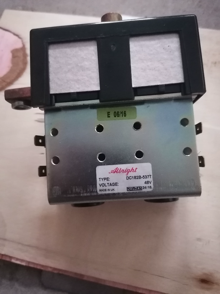

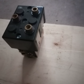
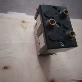
Brand: Albright (UK)
Model: DC182B-537T
Matching Controller Code: ZAPI B4DC21 (48V Traction Reversing Contactor)
Type: Integrated DC motor forward/reverse reversing contactor (Double-pole double-throw reversing structure)
Core Electrical Parameters
- Coil Voltage: DC 48V
- Maximum Main Circuit System Voltage: 48VDC
- Continuous Thermal Current Ith: 150A
- Intermittent Rated Current
30% Duty Cycle: 275A
50% Duty Cycle: 210A
60% Duty Cycle: 195A
- Structural Features: Double-break silver alloy main contacts; built-in interlock protection (prevents simultaneous actuation of forward and reverse coils. If both coils energized simultaneously, contact circuit remains open to avoid short circuit)
- Terminals
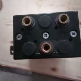
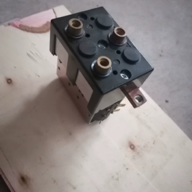
Main Power Terminals: M8 bolts
Coil Control Terminals: 6.3mm spade terminals
- Net Weight: ≈1.66~1.77kg
- Operating Ambient Temperature: -25℃~+70℃
Typical Applications
Direction reversal for traction motors on 48V electric forklifts, electric pallet trucks and tow tractors;
Compatible with ZAPI, CURTIS 48V traction controllers, widely fitted on Linde, Jungheinrich and domestic/imported warehouse vehicles.
Directly Interchangeable Models
DC182B-7 (Old version, identical mounting dimensions and pin layout)
DC182B-699, DC182B-733 (Linde OEM replacement part numbers)
⚠️ Distinguish other models in the series:
DC182B-726L → 24V coil; DC182B-581T → 80V coil, NOT interchangeable
Common Fault Conditions
- Forward travel normal, weak or no reverse movement (or reverse failure) → Single side main contact erosion
- No movement in either direction → Open coil circuit or faulty control wiring
- Audible chattering and severe overheating during actuation → Oxidized contacts or insufficient coil supply voltage
- Controller power-on leads to power device burnout: Never bypass the internal interlock to drive both coils simultaneously
Key Notes for Procurement & Replacement
- Suffix 537T denotes the 48V coil variant; suffix must be retained when placing orders;
- Two versions available on the market: Genuine UK original and domestically manufactured compatible copies. Overall mounting dimensions are similar, but contact material and electrical service life differ significantly;
- Tightening torque for main terminals: ≤9N·m; avoid excessive bending of coil spade terminals.
Service Life Parameters of Albright DC182B-537T (DC182 Series)
- Official Rated Service Life (Original DC182 Series Datasheet)
- Mechanical Life (No-load operation)
>5,000,000 operating cycles
Pure mechanical operation with zero current through main circuit, theoretical maximum limit.
- Electrical Life (48V DC motor inductive load, forklift reversing duty cycle)
Albright does not publish a single fixed value; range defined by industry standards and field vehicle data:
Ideal operating conditions (smooth start-stop, current ≤150A, controller soft reversing, low arcing): 250,000~450,000 reversing cycles
Harsh operating conditions (frequent rapid start-stop, heavy gradient loads, high inrush current): 80,000~200,000 cycles until failure
⚠️ Critical distinction: Electrical service life is far shorter than mechanical service life. Failures of DC contactors are almost exclusively caused by main contact erosion from electric arcs, mechanical structure failure is rare.
- Converted Actual Operating Hours for 48V Warehouse Forklifts
Based on electric pallet trucks and compact electric counterbalance forklifts:
Light-duty warehouse operation: 300~600 direction changes daily → Typical service life 1.5~3 years
Heavy-duty, high-frequency loading/unloading and short-distance yard transport: 800~1500 direction changes daily → Contact degradation commonly occurs within 6~18 months
Early warning symptoms: Weak forward/reverse traction, contactor overheating, increased contact resistance, controller current limiting alarms.
- Main Factors That Accelerate Service Life Degradation (Specific to DC182B-537T Reversing Contactor)
- Absence of controller soft reversing, direction switching under high current generating severe arcing (Most common cause)
- Low battery voltage, insufficient coil supply voltage leading to incomplete contact closure and persistent arcing
- Loose main terminal bolts, overheating accelerates contact oxidation and ablation (Recommended tightening torque: 8~9N·m)
- Dusty or humid operating environment causing surface oxidation of contacts
- Circuit faults resulting in temporary simultaneous energization of forward and reverse coils (Internal mechanical interlock only prevents short circuit damage, violent arcing will still occur)
- Genuine Original vs Domestic Compatible Copies
Genuine UK Albright DC182B-537T: Silver cadmium oxide contacts with strong arc resistance, meets the service life range above;
Domestic aftermarket copies: Downgraded contact materials, electrical service life is typically only 30%~60% of original units.
- Simple Inspection Method to Identify End-of-Life Contacts
Measure resistance of both main circuits with power disconnected:
New genuine unit single-pole resistance: ≈40~80μΩ;
If single-side contact resistance >250μΩ, contacts are severely eroded, replacement should be scheduled in short term.
Complete Guidelines for Judging Main Contact Replacement of Albright DC182B-537T
DC182B-537T is a 48V bidirectional DC reversing contactor equipped with two independent sets of main contacts (forward circuit and reverse circuit). Failure of either set requires replacement. Below is a 4-tier evaluation standard including static off-line measurement, live running test, visual inspection and fault symptoms, with defined threshold values and operating procedures.
Safety Precondition: Disconnect vehicle battery and wait for capacitor discharge before operation!
- Static Offline Measurement (Primary Priority Test)
Terminal Definition
Four top M8 power copper terminals:
A1, A2 → Motor connection;
B1, B2 → Battery bus connection.
Forward actuation: A1-B1 conducting; Reverse actuation: A2-B2 conducting.
Required Measuring Instrument
Digital Multimeter with milliohm measurement function (milliohm range preferred)
- Apply DC48V separately to forward coil to engage forward position
Measure resistance between A1 ↔ B1
- Apply DC48V separately to reverse coil to engage reverse position
Measure resistance between A2 ↔ B2
✅ Acceptance Standard
Brand-new genuine unit: 40μΩ ~ 90μΩ
⚠️ Warning Threshold (Prepare spare unit, replace shortly)
Single-side resistance ≥ 200μΩ
❌ Mandatory Replacement Threshold
Single-side resistance ≥ 300μΩ;
Resistance difference between two sets>150μΩ (Unilateral contact ablation causes uneven current distribution)
Important Reminder:
Do not rely solely on multimeter continuity beep mode! Continuity function only detects open/closed state and cannot identify high resistance caused by contact ablation. Contacts may still conduct under light load yet overheat and generate large voltage drop under high current.
- Live Dynamic On-Vehicle Test
Perform safe road test under permitted conditions, use multimeter DC voltage range:
- Operate forklift under full load, maintain steady travel
- With contactor engaged, measure voltage drop across the corresponding conducting terminals
✅ Normal condition: Voltage drop ≤0.3V
⚠️ Warning condition: Voltage drop 0.3V~0.6V
❌ Mandatory replacement: Voltage drop>0.6V
Principle: I²R heating; higher voltage drop generates severe contact overheating and risks contact welding.
III. Visual Inspection After Top Cover Removal
Remove upper housing cover and inspect silver contacts:
- ✅ Good condition: Smooth contact surface with only uniform light arc discoloration; no pits or built-up metallic burrs
- ⚠️ Moderate wear: Local pits and metal nodules, effective contact area less than 70% of original dimension
- ❌ Immediate replacement required:
Obvious molten pits or large-area ablation on contacts;
Contact welding or sharp metallic protrusions;
Severe contact misalignment, effective contact area less than 50%;
Note: Minor black oxide layer can be cleaned with anhydrous alcohol and lint-free cloth. Pitting damage is irreversible. Contact grinding is only temporary emergency solution and drastically shortens remaining service life; long-term use is not recommended.
- Typical Vehicle Fault Symptoms of Aged Contacts
If multiple symptoms appear, shut down equipment and inspect contacts immediately:
- Strong forward traction but weak reverse traction, or asymmetric power output (Typical symptom of unilateral contact wear)
- Vehicle speed limiting and frequent controller current limiting alarms under heavy gradient load, normal operation under no-load
- Contactor housing temperature rises significantly after short operation (Far exceeding normal temperature rise)
- Audible continuous “hissing” arcing noise during initial actuation
- Excessively high temperature on main wiring terminals, discoloration of bolt surfaces
- Common Misunderstandings
- ❌ Misconception: If contactor actuates and vehicle runs, contacts are intact
Many worn contacts maintain conduction under light load yet fail under heavy load due to elevated resistance;
- ❌ Misconception: Grinding contacts provides permanent repair
Grinding thins silver contacts, making them more vulnerable to arc penetration and greatly reducing electrical life;
- ❌ Misconception: Only test one set of contacts
This reversing contactor has two independent contact sets; ablation frequently occurs on only one side;
- ❌ Misconception: Directly judge contact failure without checking coil voltage
Insufficient coil supply voltage causes incomplete closure and persistent arcing. Verify control voltage before concluding contact damage.
- Quick Checklist for On-Site Maintenance
If any condition is met → Arrange replacement of contactor assembly
- Main circuit resistance after actuation>300μΩ, or resistance difference between two contact sets>150μΩ
- Continuous contact voltage drop>0.6V under full load operation
- Contact surface has molten pits, nodules or drastically reduced effective contact area
- Asymmetric forward/reverse traction, heavy-load current limiting, persistent contactor overheating
Supplementary Advice
Albright does NOT supply separate contact repair kits for DC182B-537T. Industry standard practice is full contactor replacement once contacts are severely worn. Some repair workshops offer refurbished contact assemblies, whose reliability is inferior to brand-new genuine units.
Operating Principle of Albright DC182B-537T (48V Bidirectional DC Reversing Contactor)
- Basic Overview
DC182B-537T is a double-pole double-throw DC reversing contactor, designed to switch forward/reverse rotation of series-wound or separately excited DC traction motors, widely applied in 48V electric forklift traction systems.
Internal assembly: Forward electromagnetic coil, reverse electromagnetic coil, mechanical interlock mechanism, two sets of independent high-current main contacts.
Model suffix 537T: Rated coil voltage DC48V
Terminal Definition (Matching Physical Unit)
Power Terminals (4 top M8 copper studs)
B1, B2: Battery positive/negative (DC power supply side)
A1, A2: Two power cables of traction motor
Control Terminals (Side spade connectors)
F+, F-: Forward coil
R+, R-: Reverse coil
- Core Structural Principle
- Two Independent Electromagnetic Drive Assemblies
Energizing forward coil generates electromagnetic force, pulling internal moving contact assembly toward forward position;
Energizing reverse coil pulls moving contact assembly toward reverse position.
- Built-In Mechanical Interlock (Critical Design Feature)
Rigid mechanical stop fitted on both drive assemblies:
✅ Physically prevents simultaneous actuation of forward and reverse coils
In case of controller fault with simultaneous voltage output to both coils, interlock blocks armature movement, both contact sets remain open.
Function: Prevent direct battery short circuit caused by simultaneous conduction of B1-A1 and B2-A2.
⚠️ Caution: Interlock serves as passive protection backup. Long-term simultaneous energization will still generate violent arcing and damage the contactor.
- Two Independent Main Current Circuits
Forward mode: Moving contact bridge connects B1 ↔ A1; motor receives forward current and rotates forward
Reverse mode: Moving contact bridge connects B2 ↔ A2; motor current direction reverses for backward rotation
Core logic: Motor rotation direction is changed by swapping motor terminal current direction, without reversing battery polarity.
III. Step-by-Step Operating Sequence
1) Forward Operation
Controller outputs DC48V to forward coil terminals F+, F-
→ Coil generates magnetic field, attracts moving armature
→ Internal copper moving conductor bridge shifts horizontally
→ B1 and A1 form reliable connection; B2 and A2 remain open
→ Current path: Battery → B1 → A1 → Traction Motor → Battery Negative → Motor forward rotation
2) Neutral (Mid) Position
No power supplied to forward and reverse coils
→ Internal return springs push moving contacts back to central position
→ Both B1-A1 and B2-A2 main circuits are disconnected
→ Motor power cut off, no output torque
3) Reverse Operation
Controller outputs DC48V to reverse coil terminals R+, R-
→ Reverse coil energized, moving contact assembly shifts to opposite side
→ B2 and A2 form reliable connection; B1 and A1 remain open
→ Current path: Battery → B2 → A2 → Traction Motor → Battery Negative → Motor reverse rotation
- Simplified Electrical Logic Diagram
“`
Power B1 ────┐ ┌── A1 → Motor
■ (Forward Contact)
Power B2 ────┘ └── A2 → Motor
Moving Conductive Bridge
“`
Left shift: B1-A1 connected
Right shift: B2-A2 connected
Middle position: All circuits open
- Key Characteristics & Common Misconceptions
- Electric Arc Generation Mechanism
Direct current has no natural zero-crossing point. Breaking high-current inductive loads (motors) creates DC electric arcs.
Continuous arc ablation of silver contacts is the root cause of contactor end-of-life.
Controllers supporting soft reversing (ZAPI/Curtis) reduce current output before switching contactor state, minimizing arcing and extending service life.
- Mechanical Interlock ≠ Electrical Interlock
Controller program must implement logic: Only forward OR reverse signal output is permitted at any single time.
Mechanical interlock is only last-resort passive safety protection and cannot compensate for programming defects.
- Coil Operating Characteristics
DC48V coil, Long-term overvoltage supply is strictly prohibited; low supply voltage results in incomplete contact closure, persistent arcing and rapid contact burnout.
Coil remains continuously energized during vehicle travel.
- Typical Control Loop for Forklift Installation
Battery → Main Contactor → DC182B-537T Reversing Contactor → Traction Motor
Traction controller receives direction switch signals → Sequentially drives forward/reverse coils to control motor rotation direction.
VII. Fault Tracing Based on Operating Principle
- Strong forward traction, weak reverse traction: Contact resistance rise caused by ablation of reverse side B2-A2 contacts
- No movement in both directions: Open coil circuit or mechanical jamming at neutral position
- Controller alarm triggered immediately after direction command: Short-circuited coil or seized interlock mechanism
- Contactor overheating: Loose main terminals or elevated resistance from ablated contacts under high current










NH42-63-318x560.png "CHINT PC-type automatic transfer switches (ATS)NH42-63/4SZ")



