 Contator,disjuntor,inversor solar,medidor elétrico,baterias solares


Selin Sistemleri, also known as Selin Systems, is a professional motion control manufacturer based in Europe. It mainly engages in servo drive systems, stepper motors and supporting industrial automation products. Isso é servo motors are widely used on production lines across Europe and the Middle East. In China, these products are mostly imported together with complete equipment, and limited official technical documents are publicly available.
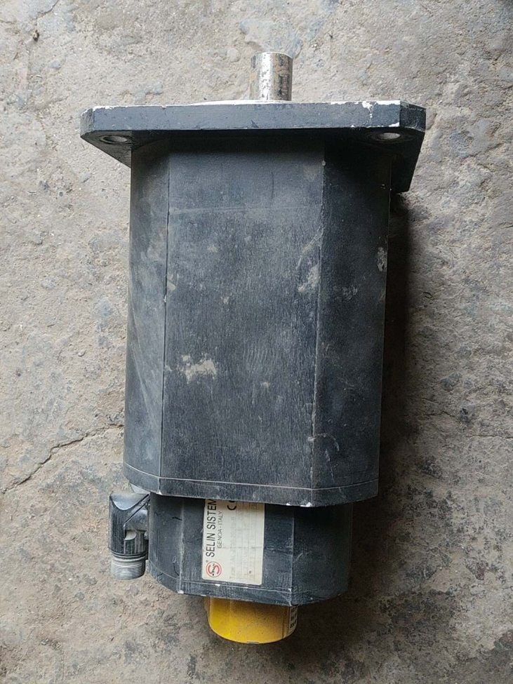
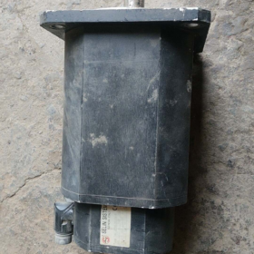
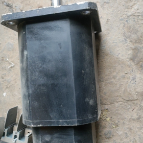
7AL-2700-20RS-B is a general-purpose AC permanent magnet synchronous servo motor from Selin 7AL Series. It is factory-fitted with a resolver for signal feedback and a power-off brake. Designed as a medium-to-low inertia industrial servo motor with high reliability, it is applicable for positioning and torque control in automotive component production, máquinas de embalagem, material handling and other fields.
- Interpretação de código modelo
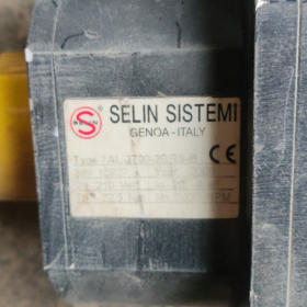
Modelo: 7AL-2700-20RS-B
| Segmento de código | Descrição | Base |
| 7AL | Série de produtos | The 7th generation AL series AC servo motors, the core general-purpose servo product line of the manufacturer. |
| 2700 | Torque nominal | Unidade: mNm, equivalente a 2.7 N*m. This naming convention is commonly adopted by European servo manufacturers. |
| 20 | Rated Speed Code | Corresponding rated speed: 2000 rpm. Industry standard rule: two digits multiplied by 100 rpm. |
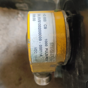
| RS | Feedback Component | Stands for Resolver. It features excellent vibration resistance, high temperature resistance and strong anti-electromagnetic interference capability, adequado para condições de trabalho adversas. |
| B | Configuration Suffix | Equipped with power-off electromagnetic brake. The output shaft will be locked once power is cut off, preventing vertical loads from falling and maintaining position during shutdown. |
- Especificações Técnicas Principais
> Observação: The following parameters are deduced based on general specifications of the same series and industry standards. Please refer to the metal nameplate on the motor body for official rated values.
3.1 Desempenho Elétrico
| Parâmetro | Especificação | Observações |
| Tipo de motor | 3-phase Permanent Magnet Synchronous Servo Motor | Sine wave driven, Isolamento classe F |
| Torque nominal | 2.7 N·m | Continuous operating rating |
| Peak Torque | Aprox.. 8.1 N·m | Short-time overload capacity, padrão 3 times overload ratio |
| Velocidade nominal | 2000 rpm | Continuous rated operating speed |
| Maximum Speed | Aprox.. 3000 rpm | Upper limit of field-weakening speed regulation |
| Potência nominal | Aprox.. 0.565 kW | Fórmula de cálculo: P = T×n/9550 = 2.7×2000/9550 |
| Tensão nominal | 3-phase AC220V | Standard low voltage for industrial servo systems |
| Feedback Type | Resolvedor | Analog sine/cosine signal feedback, adaptable to harsh environments |
| Brake Specification | Power-off Electromagnetic Brake | Tensão nominal: CC24V; Static holding torque ≥ Rated torque |
| Classe de isolamento | Classe F | Maximum withstand temperature of winding: 155℃ |
3.2 Mecânico & Parâmetros de montagem
| Parâmetro | Especificação | Observações |
| Flange Size | Standard 80mm square flange | Standard 80mm frame for motors with torque ranging from 2 N·m to 3 N·m |
| Output Shaft Diameter | φ19mm with parallel keyway | Standard shaft diameter for 80mm frame industrial motors |
| Tipo de montagem | Montagem de flange, horizontal / vertical installation available | Equipped with spigot for positioning |
| Proteção de entrada | IP65 (excluding shaft extension) | Dust-proof and water spray resistant, suitable for general industrial workshops |
| Peso | Aprox.. 2.8~3.5kg | Typical weight for brake-equipped models |
| Saída de cabo | Direct cable type | Three independent cables for power, resolver feedback and brake respectively |
3.3 Parâmetros Ambientais
| Parâmetro | Especificação |
| Temperatura operacional | 0 ~ +40 ℃ (No freezing or condensation) |
| Temperatura de armazenamento | -20 ~ +80 ℃ |
| Resistência à vibração | 10~55Hz, double amplitude 0.15mm, X/Y/Z three axes |
| Altitude Rating | ≤1000m (Derating necessário para altitudes mais elevadas) |
- Matching & Guia de seleção
4.1 Unidades compatíveis
It is recommended to use the matching servo drives of Selin Sistemleri. The drive must support resolver communication protocol and be rated for 0.75kW. If the original drive is unavailable, general-purpose servo drives with resolver support can be used as alternatives. Encoder phase auto-tuning must be completed after replacement.
4.2 Parameter Verification Methods
- Check the metal nameplate on the motor side to confirm rated voltage, poder, torque, velocidade, insulation class and other rated data.
- Count cable sets: Brake-equipped motors have 3 cable sets (cabo de alimentação, resolver feedback cable, brake cable).
- Measure flange mounting hole pitch, spigot diameter and shaft diameter to verify mounting compatibility.
4.3 Recomendações de modelos alternativos
If the original model has long lead time or high cost, equivalent servo motors with identical mounting dimensions and performance are recommended as follows:
| Marca | Modelo | Parâmetros principais | Compatibilidade de montagem |
| Yaskawa | SGM7J-08AFC6E | 0.75kW, 2.39N*m, 3000rpm; customizable for 2000rpm + freio + resolvedor | Fully compatible with 80mm flange |
| Delta | ECMA-C20807SS | 0.75kW, 2.39N*m, 3000rpm, com freio | Identical mounting holes for 80mm flange |
| Inovação | ISMH1-75B30CB-U231Z | 0.75kW, 2.39N*m; customizable for resolver + freio | Fully compatible with 80mm frame |
- Standard Wiring Definition
General wiring definition for 80mm frame servo motor with resolver and brake (Wire colors may vary among manufacturers. Verify before wiring).
| Cable Group | Core Marking | Função |
| Cabo de alimentação | Você, V, C | 3-phase power input |
| Cabo de alimentação | Educação Física (Green-Yellow) | Terra protetora |
| Resolver Cable | R1, R2 | Resolver excitation winding |
| Resolver Cable | S1, S2, S3, S4 | Sine & cosine signal windings |
| Resolver Cable | Escudo | Single-end grounding for anti-electromagnetic interference |
| Brake Cable | BR+, BR- | Brake power input, normally DC24V |
- Aplicações Típicas
- Automotive Component Production Lines: Manipulators for material loading/unloading in stamping processes, positioning of welding fixtures, station control on conveyor lines. Resolver feedback adapts to workshop conditions with vibration and oil contamination.
- Vertical Lifting Mechanisms: Z-axis modules, elevators and stackers. The brake prevents load falling when power fails.
- Embalagem & Máquinas de impressão: Feed shafts, tension control and cutting positioning. Medium-to-low inertia design meets requirements for frequent high-speed start and stop.
- General Automation Equipment: High-precision positioning for feed axes of machine tools, textile machinery and ceramic machinery.
- Matriz de solução de problemas
| Fenômeno de falha | Causa raiz | Soluções |
| Motor fails to run, drive reports encoder error | 1. Loose or broken resolver cable | 1. Reconnect feedback connector and test cable continuity |
| 2. Abnormal excitation power for resolver | 2. Measure excitation output voltage of the drive | |
| 3. Mismatched encoder protocol on drive | 3. Set the drive feedback type to Resolver | |
| Motor vibrates and generates abnormal noise during operation | 1. Mismatched servo gain parameters | 1. Run auto-gain tuning and reduce rigidity parameters |
| 2. Inércia de carga excessiva | 2. Calculate load inertia ratio and extend acceleration/deceleration time | |
| 3. Worn motor bearing | 3. Rotate the shaft manually after power off to check for jamming and abnormal sound | |
| Large positioning deviation | 1. Resolver signal affected by electromagnetic interference | 1. Single-end grounding for cable shield; route feedback cables separately from power cables |
| 2. Excessive mechanical backlash | 2. Check backlash of lead screw and gear reducer and perform mechanical compensation | |
| 3. Incorrect electronic gear ratio setting | 3. Recalculate and reset electronic gear ratio | |
| Brake malfunction, shaft rotates freely | 1. Abnormal brake supply voltage | 1. Measure voltage across brake terminals to confirm normal DC24V supply |
| 2. Open circuit of brake coil | 2. Measure coil resistance to check for open circuit | |
| 3. Severe wear of friction plate | 3. Replace brake assembly if worn out | |
| Motor overheat alarm | 1. Continuous overload operation | 1. Reduce load or extend acceleration/deceleration time to avoid long-term overload |
| 2. Excessively high ambient temperature and poor heat dissipation | 2. Melhorar a ventilação e a dissipação de calor; avoid direct sunlight and enclosed installation | |
| 3. Incorrect current parameters on drive | 3. Check motor rated current and correct relevant drive parameters |
- Prohibited Operations & Regras de segurança
- Electrical Rules: Do not apply voltage beyond rated value. Do not run power cables and feedback cables in the same conduit. Do not plug/unplug feedback connectors when powered on. Do not reverse brake power polarity.
- Mechanical Rules: Do not strike the motor shaft radially. Do not operate continuously beyond rated torque and speed. Do not apply radial/axial load exceeding the allowable limit on the shaft end.
- Environmental Rules: Do not use in flammable, explosive or highly corrosive atmosphere. Do not immerse the motor in water or expose it to direct water spray for a long time. The shaft extension is not waterproof.
- Brake Rules: Do not activate the brake while the motor is running at high speed. The brake is only for static holding after shutdown, not for dynamic braking.
- Commissioning Rules: Resolver phase auto-tuning is mandatory after drive replacement. High-speed operation is forbidden before phase calibration, otherwise the motor may run out of control and get damaged.
Lista completa de modelos & Introduction of Selin Sistemleri 7AL Series Servo Motors
> Document Note: Selin Sistemleri is a regional industrial motion control manufacturer with limited publicly released full-range catalogs. The content below is compiled according to the brand’s unified coding rules and general specification standards of European servo motors. The naming rule is fully consistent with 7AL-2700-20RS-B, for model verifcation and replacement reference. Refer to official manuals or motor nameplates for exact rated parameters.
- Visão geral da série
The 7AL Series is Selin’s core line of 3-phase permanent magnet synchronous AC servo motors. Featuring medium-to-low inertia and wide compatibility, the power range covers 0.05kW ~ 2.2kW. Multiple feedback options are available, including incremental encoder, resolver and absolute encoder, together with optional power-off brake. This series is widely applied in packaging machinery, manuseio de materiais, automotive component production lines and general automation equipment.
- Unified Naming Rule
Fixed format: `7AL [Torque Code] [Speed Code][Feedback Code] [Configuration Suffix]`
| Segmento de código | Rule | Definition of Optional Codes |
| 7AL | Fixed series code | The 7th generation AL general-purpose servo motor series |
| Torque Code | 4 dígitos, unidade: mNm | Indicates rated torque, por exemplo. 2700 = 2.7 N·m |
| Speed Code | 2 dígitos, value × 100 rpm | 15 = 1500rpm; 20 = 2000rpm; 30 = 3000rpm |
| Feedback Code | Letters / letter combinations | E = Incremental Encoder; RS = Resolver; AB = Absolute Encoder |
| Configuration Suffix | Opcional | No suffix = Without brake; B = With power-off electromagnetic brake |
- Lista completa de modelos
Classified by frame size and torque grade:
3.1 60mm Quadro (Low Torque Range)
| Modelo Completo | Torque nominal | Velocidade nominal | Feedback Type | Freio | Potência nominal (Calculated) |
| 7AL-0400-30E | 0.4 N·m | 3000 rpm | Incremental Encoder | Não | 0.126 kW |
| 7AL-0400-30E-B | 0.4 N·m | 3000 rpm | Incremental Encoder | Sim | 0.126 kW |
| 7AL-0600-30E | 0.6 N·m | 3000 rpm | Incremental Encoder | Não | 0.188 kW |
| 7AL-0600-30E-B | 0.6 N·m | 3000 rpm | Incremental Encoder | Sim | 0.188 kW |
| 7AL-0900-20E | 0.9 N·m | 2000 rpm | Incremental Encoder | Não | 0.188 kW |
| 7AL-0900-20RS | 0.9 N·m | 2000 rpm | Resolvedor | Não | 0.188 kW |
| 7AL-0900-20RS-B | 0.9 N·m | 2000 rpm | Resolvedor | Sim | 0.188 kW |
3.2 80mm Quadro (Medium Torque Range, Modelos Principais)
| Modelo Completo | Torque nominal | Velocidade nominal | Feedback Type | Freio | Potência nominal (Calculated) |
| 7AL-1300-30E | 1.3 N·m | 3000 rpm | Incremental Encoder | Não | 0.408 kW |
| 7AL-1300-30E-B | 1.3 N·m | 3000 rpm | Incremental Encoder | Sim | 0.408 kW |
| 7AL-2000-20E | 2.0 N·m | 2000 rpm | Incremental Encoder | Não | 0.419 kW |
| 7AL-2000-20RS | 2.0 N·m | 2000 rpm | Resolvedor | Não | 0.419 kW |
| 7AL-2000-20RS-B | 2.0 N·m | 2000 rpm | Resolvedor | Sim | 0.419 kW |
| 7AL-2700-20RS-B | 2.7 N·m | 2000 rpm | Resolvedor | Sim | 0.565 kW |
| 7AL-2700-20E | 2.7 N·m | 2000 rpm | Incremental Encoder | Não | 0.565 kW |
| 7AL-2700-20E-B | 2.7 N·m | 2000 rpm | Incremental Encoder | Sim | 0.565 kW |
| 7AL-2700-15RS | 2.7 N·m | 1500 rpm | Resolvedor | Não | 0.424 kW |
3.3 90/110mm Quadro (High Torque Range)
| Modelo Completo | Torque nominal | Velocidade nominal | Feedback Type | Freio | Potência nominal (Calculated) |
| 7AL-4000-20RS | 4.0 N*m | 2000 rpm | Resolvedor | Não | 0.838 kW |
| 7AL-4000-20RS-B | 4.0 N*m | 2000 rpm | Resolvedor | Sim | 0.838 kW |
| 7AL-5500-15RS | 5.5 N*m | 1500 rpm | Resolvedor | Não | 0.864 kW |
| 7AL-5500-15RS-B | 5.5 N*m | 1500 rpm | Resolvedor | Sim | 0.864 kW |
| 7AL-7200-15RS | 7.2 N*m | 1500 rpm | Resolvedor | Não | 1.131 kW |
| 7AL-7200-15RS-B | 7.2 N*m | 1500 rpm | Resolvedor | Sim | 1.131 kW |
- Matching Drive Series
All 7AL series servo motors are compatible with Selin ASD-7A series servo drives, matched by power rating:
0.1~0.2kW: ASD-7A-0123
0.4~0.75kW: ASD-7A-0423 / ASD-7A-0723
1.0~1.5kW: ASD-7A-1023 / ASD-7A-1523
> The drive must match the motor feedback type. Drives with resolver interface are required for resolver-equipped motors. Encoder phase auto-tuning is required when using third-party drives.
- Model Verification Methods
- Check the metal nameplate on the motor body to confirm rated voltage, torque, velocidade, feedback type, insulation class and other parameters.
- Count cable sets: 3 sets for brake-equipped motors (cabo de alimentação, feedback cable, brake cable); 2 sets for non-brake models.
- Measure flange hole pitch, spigot diameter and shaft diameter to determine frame size: 60mm frame = 60mm flange; 80mm frame = 80mm flange; 90mm frame = 90mm flange.

 Controlador de temperatura de selagem térmica por impulso")


 Relé")
")


NH42-63-318x560.png "Chaves de transferência automática tipo PC CHINT (ATS)NH42-63/4SZ")


