 Контактор,автоматический выключатель,солнечный инвертор,электрический счетчик,солнечные батареи

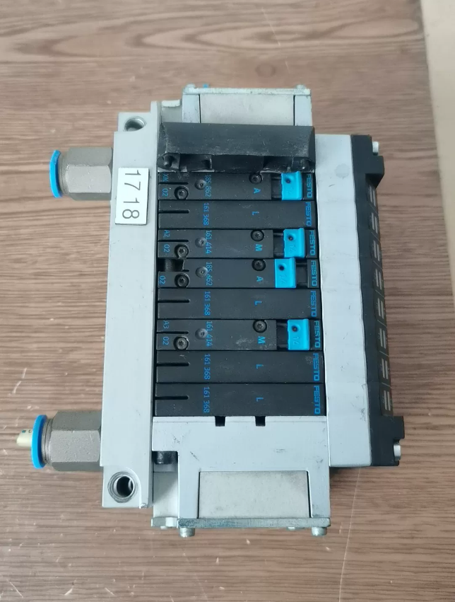

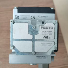
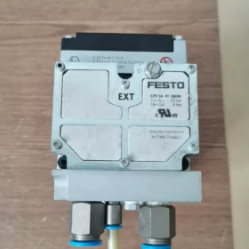
ВЕЧЕРИНКА CPV10-GE-MP-8 Valve Terminal Electrical Interface Module (Номер заказа. 18255)
The official model designation is CPV10-GE-MP-8, corresponding to Festo’s unique material order number 18255. It is a universal multi-pin electrical connection base for CPV10 series compact valve terminals.
Обзор продукта
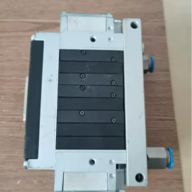
CPV10-GE-MP-8 is the standard multi-pin electrical interface module for Festo CPV10 compact valve terminals, serving as the electrical access component of the valve terminal system. It is compatible with CPV10-size valve slices and supports expansion of up to 8 solenoid valve slices. Equipped with a standard centralized D-Sub 25-pin connector, the module realizes power supply and control signal transmission for all valve positions via a single cable. Built-in reverse polarity protection and electrical isolation circuits are integrated. When combined with CPV10 valve slices and air circuit bases, a fully integrated valve terminal assembly is formed, drastically reducing on-site wiring workloads. It is widely adopted in pneumatic control applications for industrial automation including packaging machinery, обработка материалов, electronics manufacturing and automotive component assembly.
Breakdown of Model Code Segments
Per Festo’s official naming standard for CPV valve terminals, each segment of the model code is defined as follows:
CPV10: Идентификатор серии продукта, short for Compact Performance Valve, representing compact high-performance valve terminals of Size 10 (small valve terminal frame)
GE: Electrical interface type, General Electrical – universal parallel electrical interface supporting direct multi-pin connection control
член парламента: Interface form, Multi-Pin connector, factory-fitted with male D-Sub 25-pin connector
8: Maximum valve position capacity, supporting cascaded expansion of up to 8 solenoid valve slices
18255: Exclusive official Festo material order number for precise procurement
Основные технические характеристики
Electrical Ratings
| Параметр Элемент | Спецификация | Примечания |
| Номинальное рабочее напряжение | DC 24V 卤10% | Standard industrial DC power supply |
| Max Current per Valve Coil | 2А | Independent output for each valve position |
| Total Maximum Load Current | 8А | Upper current limit for all valve positions combined |
| Electrical Connector | Male D-Sub 25-pin | Standard DB25 connector |
| Electrical Isolation | Isolation between valve drive circuit and common ground | Optocoupler isolation protection |
| Функции защиты | Reverse power polarity protection, basic overcurrent protection | Prevents component burnout caused by incorrect wiring |
| Режим управления | Parallel direct control with independent signal per valve position | Matches PLC digital output modules |
Механический & Параметры окружающей среды
| Параметр Элемент | Спецификация | Примечания |
| Maximum Compatible Valve Positions | 8 | Universal for all CPV10 series valve slices |
| Тип монтажа | DIN 35mm rail mounting / wall mounting via side holes | DIN rail clip supplied as standard |
| Enclosure Rating | IP65 (after proper installation and full tightening) | Suitable for general industrial environments |
| Net Weight | Приблизительно. 151г | Interface module body only |
| Рабочая температура окружающей среды | -5℃ ~ +50℃ | Non-condensing conditions |
| Хранилище & Transport Temperature | -20℃ ~ +70 ℃ | |
| Corrosion Resistance Class | CRC 2 Moderate Corrosion Resistance | Meets requirements for indoor industrial applications |
| Код ТН ВЭД | 85371090 |
Standard Built-in Functions & Factory Supply Scope
Onboard Standard Functions
- 25-pin Centralized Electrical Interface: Single DB25 connector handles control for 8 valves plus common power supply, greatly cutting on-site wiring volume
- Reverse Polarity Protection Circuit: Avoids component damage if power supply polarity is reversed, improving fault tolerance during field wiring
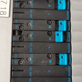
- Valve Position Status Indication Channel: Works with onboard LEDs on valve slices to visually display the switching status of each channel
- Standardized Stackable Construction: Seamless assembly with CPV10 valve slices and air bases with integrated positioning slots
- IP65 Rated Sealed Housing: Hermetic structural design resistant to dust, splashing water and typical industrial contaminants
Standard Accessories Included in Carton
- DIN rail mounting fixing clip
- Terminal end plate and sealing gasket for valve terminal
- Stacking fixing screw assembly
- Multilingual Quick Installation Guide
- Product Certificate of Conformity
Compatible Components & Возможность расширения
Supported Valve Slice Models
This interface is exclusively compatible with CPV10 series valve slices. Common matching models are listed below:
3/2-way valve slices: CPV10-M1H-2X3-GLS-M7
5/2-way valve slices: CPV10-M1H-5JS-M7, CPV10-M1H-5/3B-M7
5/3-way valve slices: CPV10-M1H-5/3G-M7, CPV10-M1H-5/3E-M7
Functional accessories: Pressure separator plates (for multi-pressure zone separation), blanking plates (for reserved expansion positions)
Возможность расширения
Supports cascading of up to 8 valve slices with mixed functional valve combinations
Enables 2~3 independent pressure air zones via separator plates
Blank blanking plates can be fitted to seal unused valve positions for future expansion
Установка & Характеристики проводки
Mechanical Installation Procedures
- Base Fixing: Clip the interface module onto a standard 35mm DIN rail, or mount it to a wall via side mounting holes
- Valve Slice Stacking: Slide CPV10 valve slices sequentially along the rail, align air sealing surfaces fully, then tighten end locking screws after stacking is complete
- End Plate Sealing: Mount the terminal end plate and sealing gasket on the opposite end of the valve terminal; full tightening ensures overall IP65 protection
- Air Tightness Inspection: Apply rated operating air pressure and check all stacking joints for air leakage; power-up only after confirming no leaks exist
Electrical Wiring Specifications
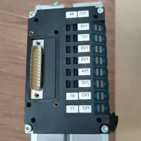
- Connector Pin Definition: Standard male DB25 connector; Приколоть 1 = DC24V positive power supply, corresponding common pin = power supply negative, remaining pins correspond to control signals for valve positions 1 к 8 respectively
- Требования к кабелю: Shielded DB25 cables are recommended with single-end grounding of shielding layer; routing alongside high-voltage power cables in the same conduit is prohibited
- Требования к источнику питания: Front-end power supply must incorporate overcurrent protection; total load current shall not exceed the rated maximum of 8A
- Wiring Prohibitions: Hot plugging/unplugging of the connector is forbidden; AC220V supply must never be connected to the interface; short-circuiting signal pins is not allowed
Типичные сценарии применения
Упаковочное оборудование: Centralized control of pneumatic actuators for filling machines, labelers and bag-making equipment
Material Handling: Integrated valve banks for sorting lines, conveyors and small loading/unloading manipulators
Производство электроники: Micro-cylinder control for SMT placement machines, insertion machines and test fixtures
Automotive Components: Pneumatic clamps and lifting actuators at assembly stations and inspection equipment
Light Industry Automation: Pneumatic control systems for food packaging and pharmaceutical filling equipment
Common Troubleshooting Matrix
| Явление неисправности | Root Cause | Step-by-Step Remedial Actions |
| All valve slices fail to actuate | Missing power supply, poor connector contact, reversed power polarity | 1. Measure power pins on DB25 connector to verify stable DC24V input |
| 2. Re-seat the connector and inspect bent, oxidized or retracted pins | ||
| 3. Verify power supply polarity and eliminate reverse connection issues | ||
| No output from single valve position | Defective corresponding pin, damaged valve slice, open signal wire | 1. Measure voltage of matching control pin to confirm normal PLC signal output |
| 2. Swap adjacent valve slices to identify whether the fault lies in the interface or valve slice | ||
| 3. Inspect internal connector pins for cold solder joints or retraction | ||
| Front-end fuse blows repeatedly | Внутреннее короткое замыкание, breakdown of valve coil, excessive total load current | 1. Remove all valve slices and test the interface alone for internal short circuits |
| 2. Install valve slices one by one to locate the shorted coil | ||
| 3. Calculate total load current to ensure it stays below the 8A rated limit | ||
| Spontaneous valve actuation / signal interference | Failed shielding, crosstalk from wiring, excessive power supply ripple | 1. Confirm reliable single-end grounding of shielded cables |
| 2. Separate control wiring from power cables and avoid shared cable ducts | ||
| 3. Measure power supply ripple and install filter power supply if necessary | ||
| Loss of enclosure protection, dust/water ingress internally | Dislodged sealing gaskets, loosely fastened end plate, under-tightened connector screws | 1. Check full installation of sealing gaskets on stacking joints and end plate |
| 2. Fully tighten DB25 connector fixing screws for tight contact | ||
| 3. Replace aged/deformed gaskets to restore original IP rating |
Operating Principle of Electrical Interface Modules for FESTO CPV10 Series Valve Terminals
The electrical interface module of CPV10 valve terminals serves as the electrical hub and access gateway for the entire valve terminal system. It fulfills five core functions: распределение мощности, signal transfer, electrical isolation, fault protection and status indication, acting as the electrical bridge between external electrical control systems (ПЛК, relay cabinets) and internal solenoid valve slices of the valve terminal. Featuring a modular stacking design, the module automatically completes electrical and air circuit docking during mechanical assembly with valve slices without secondary internal wiring, ultimately realizing electro-pneumatic conversion control: electrical signal input → pneumatic signal output.
- Overall Structure & Core Composition
Taking the widely used CPV10-GE-MP-8 (multi-pin parallel interface, Order No.18255) as the representative model, the electrical interface module internally integrates four functional circuit groups housed entirely within a sealed enclosure, achieving IP65 protection after full assembly:
- Power input & distribution circuit
- Signal isolation & drive circuit
- Electrical protection circuit
- Status indication circuit
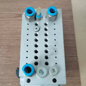
The left side of the module hosts the external electrical port (standard DB25 multi-pin connector), while the right side features the internal stacking interface (integrated pin header + air sealing surface). When stacked with CPV10 valve slices, electrical contacts and air channels are mated and locked simultaneously to achieve mechatronic integration.
- Operating Principle of Sub-Modules
- Входная мощность & Distribution Circuit
Input Preprocessing: External industrial DC24V power enters the module via the multi-pin connector and first passes through a preprocessing unit consisting of reverse polarity protection and EMI filter circuits. These suppress surge and ripple interference on power lines and prevent burnout of internal components and valve coils caused by wiring errors at the source.
Dual-Branch Power Distribution: Filtered power is split into two independent branches to separate load power and logic power supply:
Load Power Branch: Internal copper busbars parallel-feed the DC24V common rail to the common terminals of all solenoid valve coils to provide drive power. The total circuit supports a maximum current of 8A with a 2A single-channel limit.
Logic & Indicator Power Branch: Regulated power supplies internal status LEDs and isolation devices with ultra-low power consumption that does not occupy the load current budget.
- Control Signal Transmission & Drive Principle
The parallel multi-pin interface adopts a direct hardwired drive + electrical isolation control logic without protocol conversion, delivering millisecond-level valve response speed:
- Signal Input: Each DC24V digital control signal output by the PLC is fed into the module via the corresponding pin of the multi-pin connector. Pins correspond one-to-one with valve positions, enabling control of all valves through a single cable.
- Electrical Isolation: Every control signal passes through an optocoupler for physical electrical separation. This prevents reverse damage to PLC output channels from field surges and crosstalk while suppressing industrial electromagnetic interference for stable control performance.
- Coil Drive: Isolated control signals trigger power switching transistors to close the power supply loop for the corresponding valve coil. Energized coils generate electromagnetic force to actuate pilot spools inside valve slices, which in turn shift main spools to switch air circuit paths and complete electro-pneumatic conversion.
- Energy-Saving Hold Circuit: An integrated current attenuation circuit supplies full pull-in current to the coil for reliable spool shifting during energization. Once the spool reaches its target position, holding current is automatically reduced to lower coil heat generation, extend service life and cut overall power consumption without compromising pull-in stability.
- Multi-Layer Electrical Protection Mechanisms
Full-link protection circuits are integrated to cover common on-site risks including miswiring, overload and interference:
Reverse Polarity Protection: The anti-reverse circuit automatically cuts off current flow if power supply polarity is reversed, protecting all components from damage; normal operation resumes after wiring correction.
Перегрузка по току & Защита от короткого замыкания: The main circuit features current limiting. Short-circuit of a single valve coil will not burn the entire interface module. Advanced variants include channel-by-channel overcurrent protection to ensure single-channel faults do not disrupt operation of other valve positions.
Overvoltage Suppression: Built-in TVS transient voltage suppressors absorb peak surge voltages on power lines to shield internal circuits and valve coils from voltage spikes.
EMC Protection: Combined full shielding housing and filter circuits comply with industrial EMC standards for stable operation under heavy electromagnetic interference.
- Status Indication Principle
Paired with onboard LEDs on valve slices, the module delivers visual status feedback for every valve channel:
Indicator LEDs are wired in parallel with matching valve coils and light up synchronously when coils are energized, intuitively displaying on/off valve status for rapid on-site troubleshooting without multimeters.
LEDs are powered by post-isolation circuits and fully isolated from external control loops to avoid impact on control signal stability and precision.
III. Electrical Interconnection Principle of Modular Stacking
CPV10 series adopts a side-insert stacking structure enabling seamless electrical interconnection between the electrical interface module and valve slices, and between adjacent valve slices via integrated side connectors:
- During stacking, male pin headers on valve slice sides precisely insert into female sockets of neighboring modules, automatically mating the common power rail, control signal lines and air channels without secondary internal wiring.
- Dedicated sealing gaskets are fitted on stacking joints. Tightening end locking screws achieves overall IP65 protection and prevents dust and splash water from penetrating internal electrical circuits.
- This design supports flexible configuration of 2~8 valve positions. Valve slices can be added or removed at any time without modifying external wiring, minimizing expansion and maintenance costs.
- Principle Differences Between Various Electrical Interface Types
Multiple electrical interface options are available for CPV10 series with distinct core principles and applicable scenarios as shown below:
| Тип интерфейса | Core Operating Principle | Typical Model Features | Сценарии применения |
| Multi-Pin Parallel Interface (член парламента) | Direct hardwired drive with optocoupler isolation, no protocol conversion | Centralized DB25 connector, простая проводка, бюджетный | Installations with few I/O points, concentrated wiring and demand for ultra-fast response |
| Fieldbus Interface | Embedded bus protocol IC decodes bus signals into multi-channel valve control signals with comprehensive diagnostic support | Supports AS-i, Profibus and other fieldbuses, enables remote diagnostics | Automated production lines with numerous I/O points, dispersed wiring and centralized maintenance requirements |
| Terminal Separate Wiring Interface | Independent terminal wiring per channel without centralized connector | Discrete single-channel terminals with high adaptability | Retrofit projects and non-standard customized equipment requiring separate wiring for each valve |
- Complete End-to-End Operating Flow (From Command to Mechanical Actuation)
Taking PLC control of cylinder extension as an example, the full working sequence is outlined below:
- The PLC output channel transmits a DC24V switching signal to the CPV10 electrical interface module via a shielded multi-pin cable.
- The signal undergoes optocoupler isolation and power amplification inside the module to close the power supply circuit for the corresponding valve coil.
- Energization of the valve coil actuates the internal pilot spool to shift, directing compressed air into the main spool drive chamber and switching the air path of the main spool.
- Compressed air flows out from the valve slice outlet through tubing into the rodless chamber of the cylinder, pushing the piston rod to extend and complete the target control action.
- The LED indicator on the valve slice lights up simultaneously to visually feedback that the valve position is energized.
- When the PLC withdraws the control signal, the valve coil de-energizes. The spool resets under return spring force, the air circuit switches back, and the cylinder piston rod retracts.


 ряд. Это стандартная модель с классом напряжения 200 В., соответствующие серводвигатели класса 2 кВт. Оснащен двойными командными интерфейсами последовательности импульсов и аналогового напряжения., он поддерживает полнорежимное управление, включая положение,")
. Это ЦП среднего класса с выдающейся экономичностью в линейке продуктов S7-1200.. Интегрирован с собственным цифровым вводом/выводом и аналоговыми входами.")
")


")
NH42-63-318x560.png "Автоматические переключатели резерва типа PC CHINT (АТС)НХ42-63/4СЗ")


