 Schütz,Leistungsschalter,Sensor,Encoder,SPS,Konverter

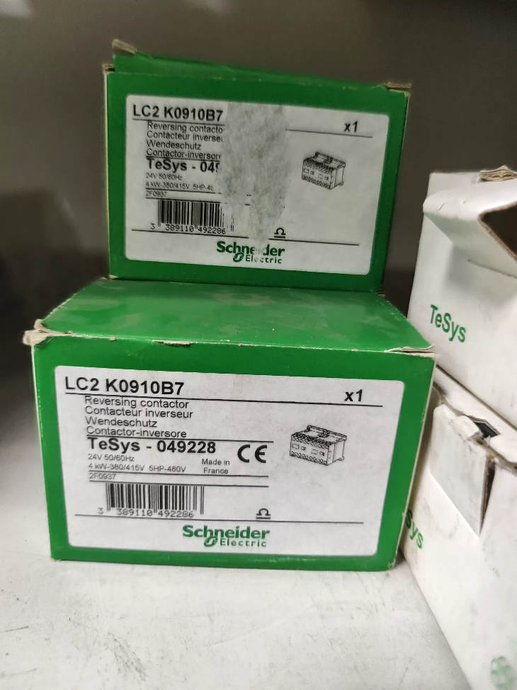

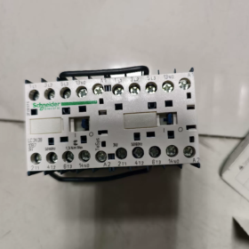
Produkt: TeSys-K 3-Polwendeschütz, Hergestellt in Frankreich, Ausgestattet mit eingebauter mechanischer Verriegelung und vormontierter Wendestromschiene
Modelldekodierung
LC2K: Wendeschützserie (LC1K steht für Single Contactor; LC2K = vormontierte Wendegruppe aus zwei Schützen)
09: AC-3 Nennbetriebsstrom 9A
01: Hilfskontaktkonfiguration 1 Normalerweise geschlossen (1NC)
B7: Spulenspannung AC24V, 50/60Hz
Grundlegende elektrische Spezifikationen
| Artikel | Parameter |
| Hauptstromkreispole | 3P-3NO |
| AC-3-Betriebsstrom | 9A |
| Nennleistung des Motors | 2.2kW(230V) / 4kW(380-415V) |
| Maximale Hauptstromkreisspannung | 690V und |
| Spule | AC24V 50/60Hz; Einschaltstrom 30VA, Hold-in 4,5 VA |
| Hilfskontakt | 1NC unverzögert |
| Konventioneller thermischer Strom Ith | 20A |
| Nutzungskategorie | AC-3, AC-3e, AC-4, AC-1 |
| Verriegelung | Integrierte mechanische Verriegelung |
| Terminalanschluss | Schraubklemmen, 0.75‑4mm² Leiter; Drehmoment 0,8-1,3 N·m |
| Montage | DIN35-Schiene / Plattenmontage mit Schrauben |
| Gesamtdimension | B90 × H58 × T57 mm, Gewicht 0,39 kg |
| Mechanische Ausdauer | 5 Millionen Zyklen; Elektrische Lebensdauer 1,3 Millionen Zyklen (AC-3) |
| Betriebsumgebungstemperatur | -25~+50℃ |
| Zertifizierungen | CCC, UL, CE, EAC |
Anwendungsszenarien
Vorwärts-/Rückwärtssteuerung des Dreiphasenmotors (Förderer, Winden, Rollen, Ventilantriebe). Die Phasenwendeschiene ist werkseitig vormontiert, Für die Verkabelung des Hauptstromkreises ist kein manueller Phasenwechsel erforderlich. Als sekundärer Schutz muss eine elektrische Verriegelung implementiert werden.
Ähnliche Referenzmodelle
LC2K0910B7: Spule AC24V, Hilfs 1NO (Normalerweise geöffnet)
LC2K0901M7: 1NC-Hilfskontakt, Spule AC220V
LC2K0901F7: 1NC-Hilfskontakt, Spule AC110V
Auswahl & Ersatznotizen
- LC2K ist eine komplette Umkehreinheit. Montieren Sie zwei separate LC1K-Schütze nicht manuell, da die werkseitig montierte Wendesammelschiene und die passende mechanische Verriegelung fehlen.
- Als heimische Alternative: Parameter überprüfen: 9A, AC24V-Spule, 1NC-Hilfskontakt, integrierte mechanische Verriegelung für Reversierbetrieb.
- Prüfstellen für Ersatzteile: Messen Sie den Widerstand beider Spulen; Überprüfen Sie die mechanische Verriegelung auf Blockierung; Überprüfen Sie die Hauptkontakte auf Ablation; Überprüfen Sie das Anzugsdrehmoment der Klemmen.
Notiz: LC2K0901B7 ist ein importiertes Modell. Der lokale Lagerbestand ist oft begrenzt und die Vorlaufzeit ist lang.
Schneider LC2K0901B7 (TeSys-K Wendeschütz) Installationshandbuch
Dieses Handbuch wurde gemäß der Originalanleitung von Schneider erstellt, für Modell LC2K0901B7, 3P, 9Und AC-3, 1NC-Hilfskontakt, AC24V 50-60Hz Spule, eingebauter mechanischer Verriegelung und vormontierter Wendestromschiene.
⚠️Sicherheitsvoraussetzung: Die Installation und Verkabelung darf nur von qualifizierten Elektrikern durchgeführt werden. Trennen Sie vor allen Arbeiten die vorgeschaltete Stromversorgung vollständig. Schutzart IP20. Das Gerät muss in einem geschlossenen Schaltschrank installiert werden, Der Betrieb im Freien ist verboten.
Inhaltsverzeichnis
- Produktübersicht
- Zusammenfassung der technischen Spezifikationen
- Umgebungsbedingungen & Mechanische Montage
- Anweisungen zur elektrischen Verkabelung
- Klemmendrehmoment & Kabelspezifikationen
- Steuerkreis & Obligatorische Verriegelungsanforderungen
- Checkliste vor dem Einschalten
- Inbetriebnahmeverfahren
- Wartung & Fehlerbehebung
- Möglichkeiten, das Original-PDF-Handbuch zu erhalten
- Produktübersicht
LC2K0901B7 ist ein werkseitig vormontierter Motor-Vorwärts-/Rückwärts-Wendeschütz, assembled from two LC1K contactors plus integrated mechanical interlock and pre-fitted reversing power busbar. Two-phase swap is completed inside factory busbar; manual phase swapping on main circuit is NOT required.
Hauptkontakte: 3 Normalerweise geöffnet; Hilfskontakt: 1 Normalerweise geschlossen (1NC) instantaneous contact
Spule: AC24V 50/60Hz; Einschaltstrom 30VA, Hold-in 4.5VA
AC-3 9A; Rated motor power 4kW@400V; 2.2kW@230V
Montage: DIN35-Schienenmontage / Plattenmontage mit Schrauben
Dimension: W90mm × H58mm × D57mm, Gewicht 0,39 kg
- Installation Ambient Conditions
- Betriebsumgebungstemperatur: -25℃ ~ +50℃; Storage temperature -50~+80℃
- Höhe: No derating ≤2000 m; derating is required above 2000 m
- Umfeld: Free of explosive dust and corrosive gas, gut belüftet; Vermeiden Sie direkte Sonneneinstrahlung.
- Schrankeinbau: Maintain ≥10 mm clearance top and bottom for heat dissipation. Side-by-side compact mounting is permitted; extra clearance is required for high-temperature environment.
- Vibration & Schock: Complies with IEC60068-2-6. Keep away from heavy-vibration equipment inside cabinet.
- Mechanische Montage
3.1 DIN-Schienenmontage (preferred)
- Hook bottom latches of contactor onto DIN35 rail.
- Drücken Sie das Schützgehäuse nach unten, bis die Riegel einrasten und fest einrasten.
- Entfernung: Hebeln Sie den unteren Riegel mit einem Schlitzschraubendreher nach unten, Schütz nach oben heben.
3.2 Plattenmontage mit Schrauben
Verwenden Sie M3/M4-Schrauben durch die Befestigungslöcher am Gehäuse. Nicht zu fest anziehen, um Risse im Kunststoffgehäuse zu vermeiden. Der Montagegrund muss eben und verzugsfrei sein.
Montageausrichtung: Vertikale Installation mit nach oben gerichteten Anschlüssen. Eine horizontale oder kopfüber liegende Montage ist verboten, was die mechanische Lebensdauer verkürzt.
- Anweisungen zur elektrischen Verkabelung
Für integriertes Wendeschütz LC2K: Die Wendestromschiene ist werkseitig montiert. Zerlegen Sie es NICHT. Bei der Demontage besteht die Gefahr eines Kurzschlusses beim Vorwärts-/Rückwärtsschalten.
Hauptstromkreisklemmen
L1, L2, L3: Dreiphasiger Stromversorgungseingang
T1, T2, T3: An Drehstrommotor U anschließen, V, W
Wichtig: Vertauschen Sie NICHT die Phasen auf der T-Seite. Die Phasenumkehr erfolgt über eine interne vormontierte Sammelschiene. Re-swapping phases on output side will result in identical rotation direction for both forward and reverse commands.
Coil terminals
A1, A2: Coil of forward contactor (AC24V)
A1, A2: Coil of reverse contactor (AC24V)
Strictly apply AC24V coil voltage. Applying 220V will burn coil instantly. Allowable coil operating voltage range: 0.8~1.15×Uc, d.h. 19.2V-27.6VAC.
Auxiliary contact terminals
13-14: 1NC normally-closed auxiliary contact, used for control-circuit interlock and status feedback.
- Klemmendrehmoment & Kabelspezifikationen
Schraubklemmenklemmen, Phillips No.2 / 6 mm flat-blade screwdriver
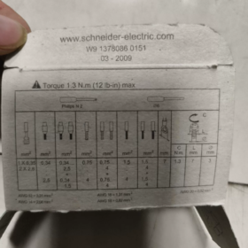
Anzugsdrehmoment: 0.8-1.3 N·m. Over-tightening cracks plastic terminal base; insufficient torque causes overheating.
Kompatible Leiter:
Solid single-core: 1.5-4 mm²
Flexible without ferrule: 0.75-4 mm²
Flexible with cable ferrule: 0.34-2.5 mm²
-Abisolierlänge: 5-6 mm. Exposed bare copper must not touch adjacent terminals to prevent phase-to-phase short-circuit.
- Control-circuit & Obligatorische Verriegelungsanforderungen
⚠️This unit is equipped with mechanical interlock only. Durch die mechanische Verriegelung kann das Risiko des gleichzeitigen Schließens beider Schütze nicht vollständig ausgeschlossen werden. Die elektrische Verriegelung über Hilfskontakte im sekundären Steuerkreis ist ZWINGEND erforderlich, Andernfalls kann es zu einem katastrophalen dreiphasigen Kurzschluss kommen.
- Mechanische Verriegelung: Der interne mechanische Mechanismus ermöglicht physikalisch das gleichzeitige Schließen nur eines Schützes. Es besteht weiterhin die Gefahr eines klemmbedingten Ausfalls.
- Elektrische Verriegelungsverkabelung: Reihen-NC-Hilfskontakt des Vorwärtsschützes im Rückwärtsspulenkreis; Reihen-NC-Hilfskontakt des Rückwärtsschützes in den Vorwärtsspulenkreis.
- Steuerversorgung: AC24V. Spulenkreise A1/A2 und A1’/A2′ sind isoliert; Vermeiden Sie eine falsche gemeinsame Verbindung.
- Empfohlene Konfiguration: Zum Motorüberlastschutz thermisches Überlastrelais einbauen; Vorgeschalteter Kurzschlussschutz durch 25A gG-Sicherung.
- Vollständige Checkliste vor dem Einschalten
- Mechanische Prüfung: Schützbetätigungsmechanismus manuell betätigen. Die mechanische Verriegelung muss ordnungsgemäß funktionieren; Ein gleichzeitiges manuelles Schließen beider Schütze darf nicht möglich sein; Der Betrieb muss reibungslos und ohne Blockierungen erfolgen.
- Überprüfung der Verkabelung: Alle Klemmen mit 0,8–1,3 N·m festgezogen; Keine losen Drahtlitzen oder freiliegendes blankes Kupfer; vormontierte Wendesammelschiene intakt und unbeschädigt.
- Spulenüberprüfung: Stellen Sie sicher, dass die Steuerspannung AC24V beträgt, um Schäden durch Überspannung zu vermeiden.
- Schaltungstest: Multimeter-Überprüfung für die korrekte Verkabelung der elektrischen Verriegelung; Kein Kurzschluss zwischen L1-L2-L3 im Hauptstromkreis.
- Motorseite: Motorisolationswiderstand normal, Motorverkabelung korrekt.
- Inbetriebnahme
- Trennen Sie die Motorlast; Betreiben Sie nur den AC24V-Steuerkreis.
- Vorwärts- und Rückwärtsbefehle separat auslösen: Es darf immer nur ein Schütz anziehen; Verriegelungsfunktion gültig. Ein gleichzeitiges Einziehen darf nicht erfolgen.
- Stromlos schalten, Motor wieder anschließen. Tanken Sie neue Energie und testen Sie nach vorne / umgekehrte Drehrichtung.
- Beobachten Sie den Betriebsstatus: Keine ungewöhnlichen Geräusche oder Überhitzung an den Anschlüssen.
Maximale Betriebsfrequenz: 3600 Operationen pro Stunde. Reduzieren Sie die Leistung für häufiges Vorwärts-Rückwärts-Wechseln.
- Wartung & Fehlerbehebung
| Fehlerphänomen | Punkte zur Fehlerbehebung |
| Spule unter Spannung, Schütz weigert sich einzuziehen | AC24V-Spulenspannung messen; Überprüfen Sie die A1/A2-Verkabelung; Überprüfen Sie die mechanische Blockierung; Spulenwiderstand messen |
| Schütz zieht an, aber Motor läuft nicht | Prüfen Sie lose oder abgenutzte Eingangs-/Ausgangsklemmen des Hauptstromkreises; Überprüfen Sie die Kontaktablation |
| Sofortige Auslösung beim Start | Bestätigen Sie, dass die Umkehrsammelschiene intakt ist; Überprüfen Sie, ob eine elektrische Verriegelung vorhanden ist; Überprüfen Sie das Risiko einer gleichzeitigen Phase-zu-Phase-Leitung |
| Lautes Betriebsgeräusch | Abweichung der Spulenspannung prüfen; Gehäuseresonanz; Schmutz auf der Oberfläche des Ankerkerns |
Referenz zur Lebensdauer: Mechanische Lebensdauer 5 Millionen Zyklen; Elektrische Lebensdauer 1,3 Millionen Zyklen unter AC-3-Bedingung.
Regelmäßige Wartung: Klemmendrehmoment nachziehen; Überprüfen Sie die Kontaktablation; Staubansammlungen entfernen.
- Zugriff auf das Original-PDF-Handbuch
- Besuchen Sie die offizielle Website von Schneider und suchen Sie nach LC2K0901B7. Laden Sie die Gebrauchsanweisung für das LC2-K-Schütz im Abschnitt „Produktdokumentation“ herunter.
- Suchen Sie im Download-Center von Schneider China nach dem Wendeschütz TeSys-K.
Notiz: LC2K0901B7 wird importiert. Das gedruckte Handbuch in Papierform ist größtenteils nur auf Englisch verfügbar und enthält keine vollständige chinesische Version. Dieses zusammengestellte Handbuch folgt strikt den Originalspezifikationen von Schneider.
Häufige Fehler von Schneider-Schützen (Gilt für die TeSys-K LC2K-Serie, auch für LC1D, LC1N usw.)
Fehlerkategorien: Einzug fehlgeschlagen; Sofortiges Aussetzen nach dem Einziehen; eingezogen, aber kein Hauptstromausgang; summendes Geräusch; Kontaktablation; Durchbrennen der Spule; Eindeutige Fehler des Wendeschützes, mit Anleitung zur Fehlerbehebung.
- Spule unter Spannung, Schütz zieht nicht vollständig an
- Keine oder unzureichende Spannung im Steuerkreis
Phänomen: Die Nennspulenspannung wurde nicht an A1-A2 gemessen; Betriebsspannung unterhalb 80% der Nennspulenspannung.
Grundursache: Fehlerhafte Steuerversorgung, Defekter Druckknopf-/Verriegelungskontakt, lose Verkabelung.
Für Umkehreinheit LC2K: Unterscheiden Sie die Vorwärtsspule A1/A2 und die Rückwärtsspule A1’/A2’.; Vermeiden Sie die Messung falscher Anschlüsse.
- Spule im Leerlauf durchgebrannt
Gemessener Spulenwiderstand unendlich; Spule sichtbar schwarz verbrannt.
Auslöser: Falsche Hochspannungsversorgung (z.B. Einspeisen von 220 V in die 24-V-Spule), anhaltende Überspannung, Hochtemperaturalterung.
- Mechanische Blockierung
Fremdkörper oder Kunststofffragmente im Inneren des Mechanismus; Schräge DIN-Schienenmontage; mechanische Verriegelung des Wendeschützes verklemmt.
Die manuelle Betätigung des Mechanismus fühlt sich schwer an und kann die geschlossene Position nicht erreichen.
- Schlechter Kontakt des NC-Hilfsverriegelungskontakts (Hochfrequenzfehler an LC2K-Umkehreinheiten)
Der oxidierte Hilfskontakt der Verriegelung unterbricht den Stromversorgungspfad der Spule.
- Spule unter Spannung, sofortiger Ausstieg / Klappern nach dem Einfahren
- Unzureichende Spulenspannung: Großer Spannungsabfall durch lange Steuerkabel; Spannung unten 85% Ue führt zu einer unzureichenden Ankerhaltekraft.
- Schmutz, Rost- oder Ölverschmutzung auf den Kontaktflächen des Ankerkerns: Der Magnetkreisabstand vergrößert sich, unzureichende Haltekraft, wiederholtes Geplapper.
- Lose Steuerstromanschlüsse, intermittierende Spannung.
- LC2K-spezifisch: Halb blockierte mechanische Verriegelung, Ein unvollständiger Mechanismusweg führt zum Ausfall.
- Schütz zieht normal an, aber der Motor läuft nicht (Kein Ausgang am Hauptstromkreis)
- Lose und überhitzte Hauptstromkreisklemmen: Ein unzureichendes Schraubendrehmoment führt zu thermischer Oxidation; Keine Lastspannung ist möglicherweise normal, Unter Last bricht die Spannung zusammen.
- Abgetragen / Hauptkontakte getrennt: Starker Einschaltstrom, Bei häufigem Wechseln entstehen karbonisierte Kontakte mit Lochfraß und hohem Kontaktwiderstand.
- Offene Phase bei vorgelagerter Versorgung: Durchgebrannte Sicherung oder beschädigter Pol des vorgeschalteten Leistungsschalters.
LC2K-Erinnerung: Gelockerte oder gelöste vormontierte Wendesammelschiene führt zur offenen Phase. Entfernen Sie niemals die werkseitig montierte Stromschiene.
- Lautes Summen / Brummgeräusch während des Betriebs
- Staub- und Fettverschmutzung auf den Kontaktflächen des Kerns, unvollständiger Magnetverschluss, typisches AC-Schütz-Brummen.
- Spulenspannung zu hoch oder zu niedrig.
- Kurzschlussring am Ankerkern gebrochen: Starker Lärm, Der Austausch des Schützes ist obligatorisch.
- Gehäuseresonanz oder lose DIN-Schienenmontage.
- Kontaktschweißen (gefährlicher Zustand)
Nach dem Ausschalten, Hauptkontakte bleiben leitend, Motor kann nicht stoppen; Bei Wendeschützen führt dies direkt zum Leiter-Leiter-Kurzschluss.
Grundursachen:
- Überlast, Kurzschlussstoßstrom; häufiges Joggen / häufiges Reversieren, bei dem die Betriebsfrequenzgrenze überschritten wird (AC-4-Dienst).
- Eine unzureichende Spulenspannung führt zu Kontaktprellen und Lichtbogenschweißen.
- Unterdimensionierte Schützleistung.
Kritisches Risiko für LC2K: Verlassen Sie sich ausschließlich auf die mechanische Verriegelung ohne elektrische Verriegelung, Durch das gleichzeitige Schließen beider Schütze entsteht ein Kurzschluss und eine Kontaktverschweißung.
- Verbrannte Spule
- Falsche angelegte Spannung: Durch die Einspeisung von 220 V Wechselstrom in die 24-VAC-Spule B7 wird die Spule sofort durchgebrannt.
- Anhaltende Überspannung oben 115% Nennspulenspannung.
- Mechanismus blockiert, Anker kann nicht schließen; Die Spule hat weiterhin einen hohen Einschaltstrom und brennt schnell durch.
- Zu hohe Umgebungstemperatur im Schrank und schlechte Wärmeableitung.
- Eindeutige Fehler für das Umkehrschütz LC2K (vorwärts-rückwärts)
- Die Drehrichtung konnte nicht geändert werden: Eine blockierte mechanische Verriegelung blockiert den Betrieb eines Schützes.
- Vorwärts funktioniert, rückwärts keine Ausgabe (oder umgekehrt): Gelockert / Freistehend vormontierte Wendesammelschiene, oder Abtragen von Hauptkontakten an einer Einheit.
- Sofortiges Auslösen bei Richtungswechsel: ① Werkseitige Wendeschiene entfernt; ② Fehlende elektrische Verriegelung führt zum gleichzeitigen Anziehen beider Schütze.
- Beschädigte Hilfskontakte: Ausfall des Rückmeldungssignals und Verlust der elektrischen Verriegelungsfunktion.
- Überhitzung
- Falsches Klemmendrehmoment: Zu geringes Drehmoment führt zu Überhitzung; Übermäßiges Drehmoment reißt den Kunststoff-Anschlusssockel.
- Unterdimensionierter Kabelquerschnitt.
- Alternde Kontakte mit hohem Kontaktwiderstand.
- Hohe Schranktemperatur, schlechte Wärmeableitung bei dicht gepackten benachbarten Geräten.
Schneller Workflow zur Fehlerbehebung vor Ort
- Ausschalten, Betätigen Sie den Schützmechanismus manuell, um auf mechanische Blockierung zu prüfen.
- Messung der tatsächlichen Betriebsspannung der Spule beim Einschalten.
- Messung des Spulenwiderstands im ausgeschalteten Zustand zur Beurteilung der Spulenintegrität.
- Bei eingezogenem Schütz, Messen Sie die dreiphasige Spannung zwischen Eingang und Ausgang am Hauptstromkreis, um den Anschluss zu lokalisieren / Kontaktfehler.
- Für Reversiereinheiten: Überprüfen Sie die mechanische Verriegelung, elektrische Verriegelungsverdrahtung und physische Integrität der vormontierten Wendesammelschiene.
Präventive Empfehlungen
- Für Wendeschütz LC2K: Eine mechanische Verriegelung ist kein ausreichender Sicherheitsschutz; Es muss eine elektrische Verriegelung implementiert werden.
- Halten Sie sich beim Anziehen der Klemmen genau an das angegebene Drehmoment.
- Reduzieren Sie die Nennleistung des Schützes für Hochleistungs-AC-4-Anwendungen mit häufigem Reversieren.
- Sorgen Sie für die Belüftung des Schranks; Führen Sie eine regelmäßige Staubentfernung durch.
Schütz-Anzug normal, Aber kein Hauptstromkreisausgang (Strom vorhanden, aber keine Lastspannung)
Phänomen: Spule unter Spannung, hörbares Einziehen, Die Statusanzeige zeigt den geschlossenen Zustand an; Allerdings liegt auf der Lastseite keine Spannung an und der Motor kann nicht laufen. Die Beschreibung gilt für das Umkehrschütz LC2K0901B7 und Allzweck-Wechselstromschütze.
- Terminal & Verkabelungsfehler (Häufigste Ursache vor Ort)
- Zu geringes Drehmoment der Hauptstromkreisschrauben, was zu einer losen Kabelverbindung führt
Die Schrauben scheinen fest angezogen zu sein, die Leiter sind jedoch nicht sicher geklemmt. Hohe Übergangswiderstände führen unter Last zum Spannungseinbruch.
Angegebenes Drehmoment für LC2K-Klemmen: 0.8-1.3 N·m. Zu niedrig → lose Überhitzung; zu hoch → Kunststoffgehäuse gerissen.
Symptom: Im Leerlaufzustand kann die Spannung normal sein, verschwindet aber, sobald Belastung aufgebracht wird; Anschlüsse weisen durch Hitze bedingte Verfärbungen auf.
- Unzureichende Abisolierlänge des Kabels, Lose Drahtlitzen sind nicht vollständig in der Klemme festgeklemmt; flexible Leiter ohne Aderendhülsen.
- LC2K-spezifischer Fehler: Gelockert, Abgelöste oder gebrochene vormontierte Wendesammelschiene. Bei Demontage der Sammelschiene kommt es zu Schäden, was zu einer offenen Phase führt. ⚠️ Werkseitig montierte Wendeschiene nicht entfernen.
- Interner Fehler des Hauptkontakts
- Abgetragen, Abgenutzte oder oxidierte Hauptkontakte mit Leitungsverlust
Der Mechanismus vervollständigt den gesamten mechanischen Hub, Dennoch können vernarbte und mit Kohlenstoff bedeckte Hauptkontakte keine elektrische Leitung herstellen.
Messmethode: Im ausgeschalteten Zustand, Halten Sie das Schütz manuell in der geschlossenen Position; Messen Sie den Widerstand L-T für jeden Pol mit einem Multimeter. Der normale Messwert liegt nahe 0 Ω; Hunderte Ohm oder ein unendlicher Widerstand weisen auf beschädigte Kontakte hin.
Auslöser: Häufiges Start-Stopp, AC-4-Joggen, Kurzschlussüberspannungen, Zustand am Ende der elektrischen Lebensdauer.
Bei einer visuellen Prüfung kann es sein, dass keine offensichtlichen Schäden erkennbar sind, während die inneren Kontaktflächen verbrannt sind.
- Mechanischer Versatz der Kontaktbaugruppe: Der Anker erreicht die geschlossene Position, aber die Hauptkontakte sind nicht vollständig komprimiert.
- Störungen der vorgelagerten Versorgung (Kann fälschlicherweise als Schützfehler diagnostiziert werden)
- Einphasige Sicherung durchgebrannt oder ein Pol am vorgeschalteten Leistungsschalter defekt. Die Eingangsphase fehlt, bevor das Schütz erreicht wird.
-Priorität bei der Fehlerbehebung: Messen Sie zunächst die dreiphasige Spannung an den Eingangsklemmen L1/L2/L3 des Schützes, um die Integrität der Versorgung zu bestätigen.
- Das vorgeschaltete thermische Überlastrelais hat den Hauptstrompfad unterbrochen.
- Spezifische Bedingungen für LC2K-Wendeschütze
- Nur eine Drehrichtung tot (weiterleiten OK / rückwärts keine Ausgabe, oder Gegenteil): Überprüfen Sie die Wendeschiene und die Hauptkontakte der entsprechenden Schützeinheit.
- Teilweise blockierte mechanische Verriegelung: Armatur erscheint geschlossen, Dennoch sind die Hauptkontakte intern nicht vollständig gedrückt.
Reihenfolge der Fehlerbehebung vor Ort
- Schritt 1: Messen Sie die dreiphasige Eingangsspannung L1, L2, L3 an den Eingangsklemmen des Schützes
Bestätigen Sie die vollständige dreiphasige Versorgung, Eliminieren Sie die vorgeschaltete offene Phase.
- Schritt 2: Bei gezogenem Schütz, Ausgangsseitige Spannung T1 messen, T2, T3
Wenn die Eingangsspannung normal ist, während eine bestimmte Ausgangsphase Null anzeigt → liegt der Fehler im Schütz (Terminals / Kontakte / Wendesammelschiene).
- Abschaltsicherer Betrieb: Schütz manuell geschlossen halten; Messen Sie den Widerstand L1-T1, L2-T2, L3-T3 mit Ohmmeter
Normal: Leitung nahe Null;
Unendlicher Widerstand: Kontakte führen nicht durch;
Hoher Widerstand: Abgelöste Kontakte oder lose Anschlüsse.
- Überprüfen Sie den Anzug der Klemmen; Überprüfen Sie die physische Unversehrtheit der vormontierten Wendesammelschiene (LC2K).
Unterscheiden Sie zwei ähnliche Phänomene
- ✅ Schütz zieht ein, kein Hauptstromausgang: Oben behandelter Fehler.
- ❌ Schütz klappert wiederholt und kann nicht geschlossen bleiben: Verursacht durch unzureichende Spulenspannung oder verschmutzte Kernflächen, unterschiedlicher Fehlermodus.
Abhilfemaßnahmen
Lose Anschlüsse: Mit dem vorgeschriebenen Drehmoment wieder festziehen; Aderendhülsen für flexible Leiter montieren.
Abgelöste Kontakte oder beschädigte Wendeschiene: Kontakte NICHT feilen oder polieren; Ersetzen Sie die Schützbaugruppe direkt. Polieren beschleunigt die Kontaktverschlechterung.
Für Umkehreinheit LC2K: Demontieren Sie nicht die werkseitig gelieferte Wendestromschiene.










NH42-63-318x560.png "Automatische Transferschalter vom Typ CHINT PC (ATS)NH42-63/4SZ")



