 Schütz,Leistungsschalter,Sensor,Encoder,SPS,Konverter

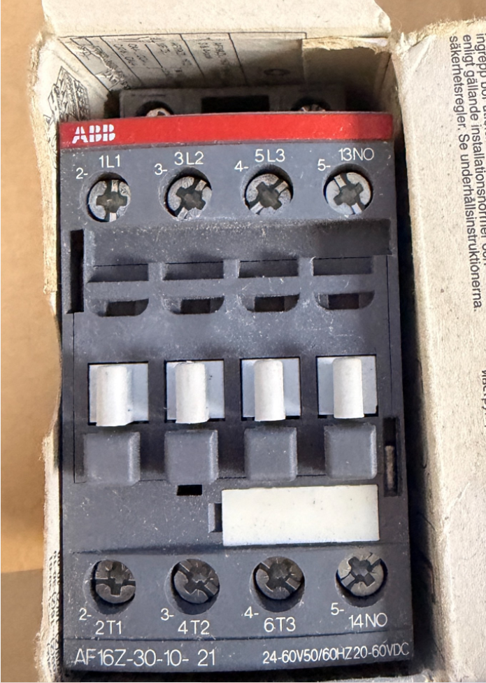

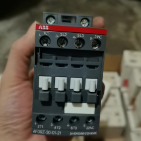
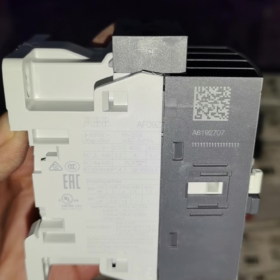
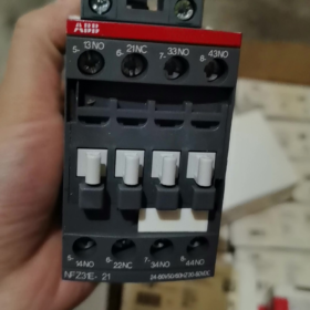
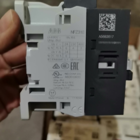
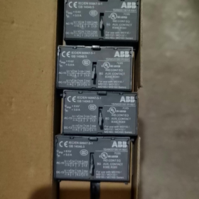
Original Factory Order No.: 1SBL176001R2110
- Modellaufschlüsselungsdefinition
AF16Z 30 10 21
- AF16Z: AF series; Z = Low-power electronic wide-range coil (direct PLC drive capable); Rahmengröße 16 Klasse
- 30: Hauptkontakte: 3 Normalerweise geöffnet (3NEIN), keine Haupt-Öffnerkontakte
- 10: Eingebaute Hilfskontakte: 1 Normalerweise geöffnet (1NEIN), 0 Normalerweise geschlossen
- 21: Coil code → Control voltage: 24~60 V AC 50/60Hz / 20~60 V DC
⚠️ Difference between AF…Z and standard AF: Extremely low coil power consumption, supports direct driving by DC24V PLC outputs, resistant to voltage dips (compliant with SEMI F47).
- Core Electrical Ratings
Maximale Hauptstromkreisspannung: 690 V und
AC-1 (ohmsche Last), ≤40°C ambient: 30 A
AC-3 (3-Phasenmotor, 400 V): 18 A, geeignet für 7.5 kW-Motor
AC-3 (690 V): 10.5 A, max. 9 kW
Montage: DIN-Schienenmontage, Schraubklemmenanschluss
Gesamtabmessungen: W 45 mm × H 86 mm × D 77 mm
Betriebstemperatur: -40~+70 °C (without thermal overload relay); -25~+60 °C (with thermal overload relay)
- Key Coil Characteristics
Wide-range AC/DC universal: AC 24~60 V / DC 20~60 V
Eingebauter Überspannungsschutz; no external RC snubber or diode required
Geringer Haltestromverbrauch, ideal for continuous energized operation
Withstands short-term voltage fluctuations and voltage drops
- Terminalidentifikation
Hauptstromkreis: 1L1-2T1, 3L2-4T2, 5L3-6T3
Hilfskontakt: 14NEIN (Normalerweise geöffnet)
- Common Alternatives & Auszeichnungen
- AF16Z-30-10-11: Gleicher Spannungsbereich, Ausgestattet mit Standard-AF-Spule (Nicht-Low-Power-Z-Spule); kann nicht direkt von stromarmen SPS-Ausgängen angesteuert werden, nicht austauschbar.
- AX16-30-10: AXE-Economy-Serie, ohne elektronische Weitbereichsspule, feste Steuerspannung; kann AF16Z nicht ersetzen.
- Für 1NO + 1NC-Hilfskontakte: Wählen Sie das Modell AF16Z-30-11-21.
- Typische Anwendungen
Vorgeschaltet von Frequenzumrichtern, Fans & Wasserpumpen, HVAC-Ausrüstung, Halbleitermaschinen, Direkte Laststeuerung des SPS-Gleichstromausgangs, Industriestandorte, die eine hohe Toleranz gegenüber Spannungsschwankungen erfordern.
ABB AF16Z-30-10-21 Schütz Technisches Installationsdokument
Bestell-Nr.: 1SBL176001R2110
- Allgemeine Sicherheitshinweise
⚠️ Komplette Installation, Verkabelungs- und Wartungsarbeiten müssen bei ausgeschalteter Stromversorgung durchgeführt werden; Das Lockout-Tagout-Verfahren ist obligatorisch. Arbeiten dürfen nur von Elektrofachkräften durchgeführt werden.
- Schutzklasse: IP20. Nur für den Schrankeinbau. Nicht im Freien installieren, nasse Umgebungen, Orte mit starker Staub- oder korrosiver Gasexposition.
- Anwendbare Normen: IEC/EN 60947-1, IEC/EN 60947-4-1; UL/CSA-zertifiziert.
- AF16Z is equipped with a low-power electronic wide-range coil with integrated surge suppression circuit. No external RC snubber or diode connection is required.
- Grundlegende Produktinformationen
2.1 Modelldefinition
AF16Z: AF series, Rahmengröße 16, Z = low-power electronic coil
30: 3 normalerweise offene Hauptkontakte
10: Eingebaut 1 normalerweise offener Hilfskontakt
21: Coil voltage range AC 24~60 V 50/60Hz / DC 20~60 V
2.2 Gesamtabmessungen
Breite 45 mm × Height 86 mm × Depth 77 mm
2.3 Rating Summary Table
| Artikel | Parameter |
| AC-1 resistive load (40 째C) | 30 A |
| AC-3-Motorlast (400 V) | 18 A, kompatibel mit 7.5 kW 3-phase motor |
| Maximale Betriebsspannung | 690 V und |
| Betriebstemperatur (ohne Thermorelais) | -40 째C ~ +70 째C |
| Betriebstemperatur (with thermal overload relay) | -25 째C ~ +60 째C |
- Mechanische Installationsspezifikationen
3.1 Montagemethoden
Two mounting options available:
- DIN-Schienenmontage (Empfohlen)
Rail standard: TS35 (35×7.5 mm / 35×15 mm)
Betrieb: Hook the bottom latch onto the rail, press down until an audible click confirms locking. For removal, use a flat screwdriver to pry the bottom latch and lift upwards.
- Base Plate Screw Mounting
Fasten diagonally using 2 × M4 screws; refer to outline drawing for mounting hole spacing.
3.2 Montageausrichtung & Freigabe
- Vertikale Montage (Klemmen oben & unten) preferred. 90° horizontal side mounting is permitted; upside-down installation is forbidden.
- Mehrere Einheiten können ohne Stromreduzierung nebeneinander montiert werden. Halten Sie zur Belüftung einen vertikalen Freiraum von ≥15 mm ein; Von wärmeerzeugenden Bauteilen wie Widerständen und Wechselrichtern fernhalten.
- Vermeiden Sie die Installation an Orten mit starken Vibrationen. Vibrationsbeschleunigung >0.5g erfordert schwingungsdämpfende Maßnahmen.
- Spezifikationen für die elektrische Verkabelung
4.1 Definition der Klemmenmarkierung
Oberer Hauptstromkreis: L1, L2, L3 (Stromanschluss)
Unterer Hauptstromkreis: T1, T2, T3 (Ausgang laden)
Nicht-UL-Anwendungen ermöglichen die Stromeinspeisung von oben oder unten; UL-zertifizierte Installationen erfordern eine Stromzufuhr über die oberen L-Klemmen.
Spulenklemmen A1, A2: Steuersignaleingang (AC/DC unpolarisiert)
Hilfskontakt 13-14: Eingebauter Schließerkontakt (1NEIN)
4.2 Kabelspezifikation & Abisolierlänge
Standard-Abisolierlänge: 10 mm
Hauptstromkreisleiter: Massives/verseiltes Kupferkabel 1–6 mm²; Für flexible Kabel werden Aderendhülsen empfohlen
Kontrolle / Hilfsstromkreisleiter: 0.75~2,5 mm²
4.3 Anzugsdrehmoment (Obligatorisch)
Hauptstromkreisklemmen: 1.5 N·m
Spule A1/A2 & Hilfskontaktklemmen: 1.2 N·m
Ein unzureichendes Drehmoment führt zu einer Überhitzung der Klemmen; Ein zu hohes Drehmoment führt zum Abreißen des Gewindes.
Empfohlene Werkzeuge: PZ2 Pozidriv-Schraubendreher / 5.5 mm flacher Drehmomentschraubendreher.
- Kritische Hinweise zur Spulenanwendung (Kernmerkmal von AF16Z)
- Spannungsbereich: AC24~60V / DC20~60V, breite Spannungskompatibilität, Direktantrieb durch SPS-Gleichstromausgänge.
- Sehr geringer Spulenhaltestromverbrauch, Geeignet für den Dauerbetrieb unter Spannung; Entspricht den SEMI F47-Anforderungen zur Spannungsabfallimmunität.
- A1 und A2 sind nicht polarisiert; Für die DC24V-Steuerung spielt die Polarität keine Rolle.
- Legen Sie keine höhere Steuerspannung an 60 V, Andernfalls wird das elektronische Spulenmodul zerstört.
- Optionale Zubehörinstallation
- Seitlich angebrachte Hilfskontakte (CA4-Serie)
Lässt sich ohne Werkzeug in die linken/rechten Seitenschlitze einrasten. Maximal 2 Sätze von seitlichen Hilfskontakten können an AF16 montiert werden.
- Mechanische Verriegelung
Installieren Sie für die Umkehrschaltungskonfiguration zwei AF16Z-Schütze, um ein gleichzeitiges Schließen und einen Kurzschluss zwischen Vorwärts- und Rückwärtsphase zu verhindern.
- Anpassung des thermischen Überlastrelais
Kompatibel mit Thermorelais der Serie TA25DU, Direkte Schnappmontage unterhalb des Schützes.
- Inbetriebnahmevorgang nach dem Einschalten
- Im ausgeschalteten Zustand: Sichtprüfung auf korrekte Verkabelung, keine metallischen Rückstände, Alle Klemmen mit dem vorgeschriebenen Drehmoment anziehen.
- Betätigen Sie den Schützmechanismus manuell, um einen reibungslosen Betrieb ohne Blockierung zu bestätigen.
- Steuerstromkreis selbstständig testen: Bemessungssteuerspannung an A1/A2 anlegen; Das Schütz muss zuverlässig einziehen und bei Stromunterbrechung sanft abfallen.
- Synchrones Schalten des Hilfskontaktes prüfen 13-14 mit Schützbetätigung.
- Schließen Sie den Hauptstromkreis für einen Testlauf im Leerlauf an; Auf ungewöhnliche Geräusche und schnellen Temperaturanstieg am Anschluss prüfen.
- 30-Minutenlastiger Betriebstest; Überprüfen Sie die Anschlusstemperatur erneut, um sicherzustellen, dass der Temperaturanstieg innerhalb der zulässigen Grenzen bleibt.
- Installationsfehler & Verbotene Praktiken
❌ Verbotene Operationen:
Freiliegende lose Litzen an den Kabelanschlüssen
Anziehen der Klemmen unter Spannung
Steuerspannung außerhalb des Bereichs von 20–60 V
Blockierung der Lüftungskanäle oberhalb und unterhalb des Schützes
Direkte Installation in Umgebungen mit brennbarem Staub oder kontinuierlicher Kondensation
Häufige Probleme nach der Installation
- Schütz klappert/instabiles Einziehen: Stellen Sie sicher, dass die Steuerspannung über dem minimalen Betriebspegel liegt; Überprüfen Sie den Spannungsabfall entlang der Steuerkabel.
- Überhitzung des Terminals: Ziehen Sie die Klemmen wieder mit dem vorgeschriebenen Drehmoment fest; Stellen Sie sicher, dass der Leiterquerschnitt ausreichend ist.
- Beim Ansteuern durch die SPS gelingt das Einfahren nicht: Bestätigen Sie, dass es sich bei der Einheit um AF16Z handelt (Spule mit geringer Leistung); Die Standard-AF16-Spule kann nicht direkt über SPS-Transistorausgänge angesteuert werden.
- Wartungsanforderungen
- Regelmäßige Überprüfung der Endtemperatur und ungewöhnlicher Geräusche.
- Vermeiden Sie wiederholtes Schalten oberhalb der Nennausschaltkapazität.
- Betreiben Sie das Schütz niemals mit entferntem Lichtbogenschutz. Tauschen Sie die komplette Einheit aus, wenn es bei den Kontakten zu starker Ablation kommt.
Mechanische Lebensdauerparameter von ABB AF16Z-30-10-21
Der AF16Z hat die gleiche mechanische Konstruktion wie der Standard-AF16. Offizielle technische Daten:
✅ Mechanische Ausdauer: 10 Millionen Schaltspiele (10×10⁶ Operationen)
Testbedingungen: Bemessungssteuerspannung, Leerlaufschaltung, Standard-Umgebungstemperatur.
Unterstützende Schlüsselparameter
- Maximale mechanische Betriebsfrequenz: 3,600 Operationen pro Stunde
Der kontinuierliche Hochfrequenzbetrieb darf diesen Grenzwert nicht überschreiten, um einen beschleunigten mechanischen Verschleiß zu vermeiden.
- Referenz elektrische Lebensdauer (hängt von der Lastart ab, nicht gleichbedeutend mit mechanischem Leben)
AC-3 (400 V Motorlast): Ca. 1,000,000 Zyklen
AC-1 (ohmsche Last): Ca. 1,600,000 Zyklen
⚠️ Die mechanische Lebensdauer stellt die mechanische Betriebsgrenze dar; Die Lebensdauer wird in der Praxis normalerweise durch elektrische Erosion von Kontakten bestimmt.
Ergänzende Bemerkungen
- Der AF16Z unterscheidet sich nur durch seine elektronische Weitbereichsspulenvariante mit geringem Stromverbrauch. Anker, Gestänge und mechanische Kontaktstruktur sind identisch mit dem Standard-AF16; Die mechanischen Lebensdauerwerte bleiben unverändert.
- Die tatsächliche mechanische Lebensdauer nimmt in rauen Umgebungen ab (starker Staub, kontinuierliche Vibration, hohe Temperatur).
- Definition der mechanischen Ausdauer: Betriebszyklen des Ein-/Ausschaltens des Schützes werden nur durch die Spule gesteuert, ohne dass eine Last an den Hauptstromkreis angeschlossen ist.










NH42-63-318x560.png "Automatische Transferschalter vom Typ CHINT PC (ATS)NH42-63/4SZ")



