 contactor,cortacircuitos,sensor,Codificador,SOCIEDAD ANÓNIMA,Convertidor

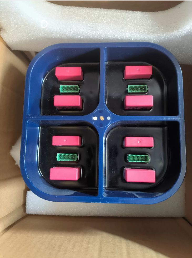

Designación completa del modelo: IPS 21-35 ANUNCIO, Código de material 3BHB017688R0001
- Información básica
Fabricante: TEJIDO (originalmente Sécheron, Suiza)
Categoría: Puerta aislada Módulo de alimentación del variador / Unidad de fuente de alimentación del variador IGCT (IPS – Fuente de alimentación aislada)
Sistemas aplicables: ABB media tensión Convertidores de frecuencia y convertidores IGCT. (ACS5000, ACS6000, Variadores de velocidad de alta potencia serie PCS6000)
Origen: Alemania / Suiza
Regla de codificación de materiales: Código de serie que comienza con 3BHBxxxxR0001 = Serie de repuestos de potencia del variador ABB
- Función principal
Suministra energía CC regulada y aislada galvánicamente a unidades de accionamiento de puerta IGCT.; logra la separación entre el circuito de potencia y el circuito de control. Equipado con sobrecorriente, protección contra cortocircuitos y subtensión. Componente estándar instalado dentro de unidades de potencia de convertidores de media tensión de alta potencia..
Concepto erróneo común: No es una placa de excitación., Módulo de E/S PLC o dispositivo semiconductor IGCT; Es una unidad de fuente de alimentación dedicada para accionamientos de puertas..
- Especificaciones eléctricas clave
| Artículo | Parámetro |
| Potencia de entrada | 110–250 VCA, 50/60 Hz (CA monofásica) |
| Salida aislada | 4 salidas CC mutuamente aisladas (fuente de alimentación para 4 juegos de placas de accionamiento de puerta IGCT) |
| Clase de protección | IP20 (para montaje interno del gabinete) |
| Temperatura de funcionamiento | -10 ℃ ~ +60 ℃ |
| Temperatura de almacenamiento | -40 ℃ ~ +85 ℃ |
| Método de enfriamiento | Refrigeración por aire natural, disipador de calor montado en la parte inferior |
| Construcción | Carcasa de plástico azul sellada., Encapsulado internamente para resistencia a la humedad y rendimiento antivibración. |
- Equipo de aplicación típico
- Convertidores de media tensión ABB ACS6000 (3kV / 6accionamientos de alta potencia kV)
- Convertidores de media tensión ABB ACS5000
- Laminadores metalúrgicos, polipastos de mina, grandes fans & bombas y otros sistemas de accionamiento de alta potencia
- Convertidores IGCT de alta potencia para tránsito ferroviario y sistemas de almacenamiento de energía
- Pieza de recambio & Pautas de reemplazo
- Modelo de reemplazo directo: Sólo 3BHB017688R0001 (IPS21-35AD) Se puede utilizar para reemplazo directo.. Other suffix variants within IPS21 series are not interchangeable due to different definitions of isolated output channels.
- Procurement Classification: Brand new original units / second-hand dismantled units. Many suppliers mislabel this product as excitation board or communication module; always verify the marking IPS21-35AD on the housing before order placement.
- Síntomas típicos de falla:
Power unit reports gate drive power fault or fiber communication interruption
Drive board LED indicators remain off after power-up; IGCT fails to trigger
Fusible interno fundido, abnormal overheating of module housing
- Decodificación de código modelo
3BHB: Prefix for ABB drive power spare parts (IGCT-related assemblies)
017688: Internal component serial number
R0001: Revision version code
IPS21-35AD: Short product name (Isolated Power Supply Series 21)
In-depth Introduction to Overcurrent Protection Mechanism of ABB 3BHB017688R0001 (IPS21-35AD)
Module Positioning: Fuente de alimentación aislada de cuatro canales para accionamientos de compuerta IGCT dentro de convertidores de media tensión ACS6000/ACS5000/PCS6000. Diseñado por Sécheron original; Sellado y encapsulado con cuatro salidas aisladas independientes para alimentar cuatro placas de control de puerta IGCT..
Nota crítica: Cuatro canales de salida funcionan de forma independiente. Cada canal está equipado con muestreo dedicado y circuitos de protección contra sobrecorriente independientes.; El módulo no implementa limitación de corriente unificada para todos los canales..
- Descripción general de la arquitectura de protección de tres niveles
- Etapa Primaria: Ciclo por ciclo (CBC) limitación de corriente de hardware para MOSFET del lado primario
- Etapa secundaria: Muestreo independiente en cuatro canales de salida., limitación activa de corriente constante (protección contra sobrecarga)
- Protección final: El cortocircuito de salida activa el modo Hipo; las fallas prolongadas activan el pestillo de apagado térmico
Distinción importante
Sobrecarga (Sobrecorriente leve): Limitación de corriente constante mantenida, el voltaje de salida cae naturalmente sin apagar el canal
Cortocircuito de salida (Sobrecorriente severa): Permite un funcionamiento intermitente para evitar que la alta corriente continua dañe las placas impulsoras y el módulo de alimentación.
Todas las funciones de protección se implementan mediante circuitos de hardware analógicos sin participación de MCU.. La lógica de protección no se ve afectada por fallas en el circuito de control o comunicación., Cumplir con los requisitos de seguridad para accionamientos industriales..
- Principio de detección de hardware
2.1 Método de muestreo actual
Una resistencia de derivación de potencia de alta precisión está conectada en serie al riel negativo de cada canal de salida aislado..
La diferencia de voltaje a través de la resistencia en derivación está condicionada por amplificadores operacionales y alimentada a comparadores de voltaje para compararlos con el voltaje de referencia de precisión interno para juzgar las condiciones de sobrecorriente en tiempo real..
Ventaja: Respuesta de nivel de microsegundos con retraso mínimo de filtrado, capaz de capturar la corriente de entrada durante el encendido del variador IGCT.
2.2 Umbrales actuales de dos niveles definidos por el diseño OEM
1) Umbral de sobrecarga (Punto límite actual I_LIM)
Activado por un aumento gradual de la carga., Corriente de fuga parcial o aumento del consumo de energía causado por el envejecimiento de las placas de accionamiento..
Modo de acción: Limitación activa de corriente constante.
La fuente de alimentación aumenta dinámicamente la impedancia de salida equivalente y fija la corriente de salida en el valor máximo preestablecido.; El voltaje de salida disminuye naturalmente a medida que aumenta la carga.. El canal permanece activo mientras la falla no se deteriore..
2) Umbral de cortocircuito (Punto de disparo por cortocircuito I_SC, superior al límite de sobrecarga)
Activado por cortocircuito directo entre terminales de salida., avería interna de la placa controladora o cortocircuito de la interfaz de fibra.
Modo de acción: Bloquear inmediatamente la salida del canal correspondiente., espere a que se solucione el retraso y luego intente reiniciar → Protección contra hipo.
- Secuencia de acción completa en dos escenarios de falla
Guión 1: Sobrecarga de salida de un solo canal (Sobrecarga Sobrecorriente)
- La corriente de carga excede el umbral de sobrecarga; El voltaje muestreado supera el nivel de referencia.
- El circuito de retroalimentación secundario ajusta el ciclo de trabajo PWM para implementar una sujeción de corriente constante
- El módulo mantiene la operación de limitación de corriente sin cerrar el canal
- Síntomas de campo: Bajo voltaje de suministro para placas de control., Indicadores LED tenues en las placas de transmisión.; Alarmas del convertidor de frecuencia Subtensión del variador / Fallo de la unidad de potencia
- Recuperación de fallas: Cuando la corriente de carga vuelve a caer dentro del rango nominal después de eliminar la sobrecarga, El voltaje de salida se restablece automáticamente sin necesidad de reiniciar el módulo.
Fenómeno de campo común: Operación de limitación de corriente a largo plazo causada por una fuga de una sola placa de accionamiento IGCT, acompañado de un lento aumento de temperatura en la carcasa del módulo.
Guión 2: Cortocircuito de salida de un solo canal (Sobrecorriente severa / Cortocircuito)
- El aumento instantáneo de corriente excede el umbral de cortocircuito
- El comparador genera señal de protección, transmitido a través del aislamiento del optoacoplador al controlador PWM del lado primario; La unidad PWM de este canal se desactiva inmediatamente
- La salida permanece bloqueada durante un período de inactividad fijo (normalmente decenas de milisegundos)
- Después de que expire el período de inactividad, Se inicia el intento de reinicio automático.
- Si el cortocircuito persiste, el apagado de protección se repite; El funcionamiento cíclico intermitente genera hipos periódicos.
- Característica visual: El indicador LED de la placa controladora correspondiente parpadea periódicamente
- Enclavamiento térmico de respaldo: El funcionamiento continuo con hipo a largo plazo provoca un calentamiento excesivo de los dispositivos de alimentación internos, Activación de protección contra sobretemperatura y cierre total.. La fuente de alimentación debe reiniciarse para restablecerse..
- Características clave (Crítico para la ingeniería in situ)
- Protección independiente para cuatro canales.
Si un canal sufre cortocircuito o sobrecarga, sólo el canal defectuoso está bloqueado; los otros tres canales mantienen el suministro de energía normal.
Recordatorio de riesgo extremo: Cuando falla una placa de accionamiento IGCT dentro de la unidad de potencia, los otros tres accionamientos IGCT permanecen energizados. El corte completo de energía y la descarga total son obligatorios antes del mantenimiento.; Nunca asuma que todos los canales están desenergizados debido a una falla de un solo canal..
- Sin lógica de enclavamiento de canal
La falla de un solo canal no cortará la entrada de CA de todo el módulo; sólo se aísla la rama de salida defectuosa.
- Lógica de recuperación automática
Fallo de sobrecarga borrado: Recuperación automática instantánea
Fallo de cortocircuito borrado: La salida se reanuda en el siguiente ciclo de reinicio sin ciclo de encendido del módulo
Sólo el bloqueo térmico activado por un cortocircuito sostenido requiere la interrupción de la alimentación de CA para restablecerse.
- Limitación de corriente máxima ciclo por ciclo del lado primario (máxima protección de respaldo)
Si varios canales hacen cortocircuito simultáneamente y la protección secundaria no puede suprimir la sobretensión instantánea, La limitación de CBC en los circuitos del interruptor primario restringe la corriente máxima primaria del transformador y previene fallas catastróficas de los interruptores de potencia., actuando como la última barrera de seguridad.
- Enlace de falla entre la protección contra sobrecorriente y el sistema convertidor ACS6000/ACS5000
- Limitación de corriente del canal IPS → voltaje de suministro reducido para la placa de accionamiento de puerta → amplitud insuficiente del accionamiento de puerta IGCT
- Estado anormal del transceptor de fibra en la placa controladora → la placa de control de la unidad de potencia detecta pérdida de señal de fibra
- El controlador del convertidor principal genera una alarma de falla: Fallo de la unidad de potencia / Fallo de alimentación del variador / Fallo de comunicación de fibra
- Nota importante: El módulo IPS no proporciona señales de contacto de falla externas cableadas. El convertidor juzga la anomalía del suministro de energía indirectamente a través del estado de comunicación de fibra de los controladores de puerta..
- Errores de juicio típicos & Pautas en el sitio
- ❌ Malentendido: La protección contra sobrecorriente de un solo canal apagará todo el módulo IPS
✅ Hecho: Cuatro canales funcionan de forma independiente; sólo el canal defectuoso entra en funcionamiento intermitente.
- ❌ Malentendido: El modo Hipo equivale a daño permanente del módulo
✅ Hecho: El modo Hipo es una respuesta de protección normal. Priorizar la resolución de problemas de cortocircuito de las placas o cableado del controlador IGCT aguas abajo; En la mayoría de los casos, el IPS reanuda su funcionamiento normal después de reemplazar la placa controladora defectuosa..
- ❌ Malentendido: La resistencia de derivación se puede poner en cortocircuito para desactivar la protección contra sobrecorriente.
✅ Estrictamente prohibido: Después de deshabilitar la limitación actual, La rotura de las placas de accionamiento provocará el desgaste irreversible del transformador interno de alta frecuencia y de los dispositivos de conmutación dentro del IPS..
- Influencia ambiental: La estructura en maceta tiene una disipación de calor limitada.; El umbral de protección varía ligeramente a temperaturas ambiente elevadas., lo que fácilmente causa limitación de corriente espuria durante la operación de verano.
- Procedimiento de prueba fuera de línea para verificación de protección contra sobrecorriente
- Aplique voltaje de entrada de 110 ~ 230 VCA al módulo
- Conecte una carga electrónica ajustable a cualquier canal de salida, aumentar gradualmente la corriente de carga; Confirme que el modo de corriente constante se activa una vez que se alcanza el límite superior nominal.
- Terminales de salida de cortocircuito directamente, verificar el parpadeo periódico del indicador LED de la unidad (firma típica de hipo)
- Eliminar la condición de cortocircuito; se reanuda la producción normal. Esto confirma la integridad total del circuito de protección contra sobrecorriente..





NH42-63-318x560.png "Interruptores de transferencia automática tipo PC CHINT (ATS)NH42-63/4SZ")



