 contactor,cortacircuitos,inversor solar,medidor electrico,baterias solares


Basic Model Definition
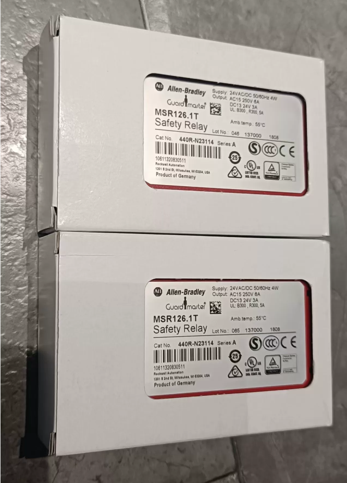
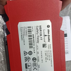
Catalog Number: 440R-N23114
Internal Model Code: MSR126.1T
Marca: Allen-Bradley (Automatización Rockwell), Guardmaster Minotaur Series
Ciclo vital: Active production model, manufactured in Czech Republic, standard 1-year warranty
- Core Electrical Specifications
2.1 Fuente de alimentación
Tensión nominal: 24VCA/CC, rango de operación: 0.85~1.1× rated voltage (20.4~26,4V)
Consumo de energía: 4W., compatible with 50/60Hz
Terminals A1/A2: Entrada de energía
2.2 Safety Inputs (Dual-channel 4-wire with cross short-circuit detection)
2 normalmente cerrado (CAROLINA DEL NORTE) safety input paths (S11-S12 / S21-S22)
Supports dual-channel emergency stop, safety door switches and safety light curtains; built-in cross-channel short-circuit fault diagnosis
Maximum input loop resistance: ≤90Ω
2.3 Reset Circuit (S33-S34)
MSR126.1T supports automatic reset and manual reset dual modes
- Reinicio automático: Short S33 and S34; outputs close automatically after faults are cleared
- Reinicio manual: Connect an external normally open reset pushbutton to S33-S34; manual push is required to restore outputs
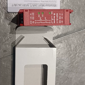
Difference from MSR126.1R: MSR126.1R only provides monitored manual reset without automatic reset function
2.4 Safety Output Contacts (Force-guided safety contacts complying with IEC 61810-3)
2 safety normally open (NO) contactos: 13-14, 23-24
Load Ratings:
DC-13: 6A/24V DC; 3A/24V DC (for frequent switching)
AC-15: 5CA/250 VCA
Tiempo de respuesta: Aprox.. 15EM; Recovery Time: 100EM
No auxiliary alarm contacts
- Safety Certification Ratings (Top Industry Standards)
ISO 13849-1: Categoría 4 / pl y
CEI 61508 / CEI 61511: SIL 3
EN 954-1: Safety Category 4, Categoría 0 Detener
Certificaciones: CE, cULus, CCC, bg, C-Tick
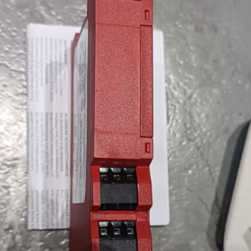
- Mechanical Dimensions & Montaje
Ancho: 22.5milímetros (compact DIN rail mounting)
Dimensión general: 110milímetros (h) × 75 mm (D) × 22,5 mm (W.)
Peso: 160gramo
Terminales: Fixed screw terminals (non-pluggable), Grado de protección IP20
Temperatura de funcionamiento: -25℃ ~ +70℃
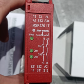
- Front Panel LED Indicator Meanings
- PWR (Verde): Steady on when power supply is normal
- CH1 (Verde): Illuminated when Channel 1 input circuit is closed
- CH2 (Verde): Illuminated when Channel 2 input circuit is closed
All three LEDs on → Safety output contacts closed; Any single channel open → Outputs cut off
- Escenarios de aplicación típicos
- Dual-channel emergency stop button circuit monitoring
- 4-wire safety door switches (with short-circuit detection)
- Cortina de luz de seguridad / light screen safety circuits
- Safety cut-off for machine tools, automated production lines and packaging equipment
Suitable for equipment requiring high safety ratings of PL e / SIL3
- Series Model Comparison for Selection
| Catalog No. | Internal Code | Modo de reinicio | Fuente de alimentación | Configuración del canal |
| 440R‑N23114 | MSR126.1T | Selectable Auto/Manual Reset | 24VCA/CC | Dual-channel 4-wire |
| 440R‑N23113 | MSR126.1R | Monitored Manual Reset Only | 24VCA/CC | Dual-channel 4-wire |
| 440R‑N23112 | MSR126T | Auto/Manual Reset | 230V y | Dual-channel 4-wire |
- Brief Wiring Logic
- Connect 24V AC/DC power to terminals A1/A2
- Wire two NC safety switches (parada de emergencia / door switches) in series to S11-S12 and S21-S22 respectively
- Short-circuit S33-S34 for automatic reset; connect an NO pushbutton in series for manual reset
- Wire the safety coil of main contactors in series across terminals 13-14 y 23-24
- Disconnection of any safety input or cross-channel short-circuit will simultaneously open both NO outputs to cut power supply
- Troubleshooting Guidelines
- PWR LED off: Power phase loss, insufficient voltage or loose wiring
- Single CH1/CH2 LED off: Corresponding channel switch open or circuit wire breakage
- Both CH1 and CH2 LEDs lit but outputs fail to close: Cross-channel short-circuit fault; power cycle to reset, or reset circuit not shorted / reset button not pressed
- soldadura por contacto: Excessive output load; replace contactors with higher capacity
Full Specifications of Safety Output Contacts for Allen-Bradley 440R-N23114
- Basic Contact Structure
- Cantidad & Tipo: 2 independent redundant safety normally open (NO) contacts at terminals 13-14 y 23-24; no auxiliary alarm contacts or delayed outputs
- Contact Construction: Force-guided safety contacts (CEI 61810-3), dual-channel redundant mechanical interlock. Single contact welding cannot maintain circuit conduction, fulfilling Category 4 / pl y / SIL3 safety architecture
- Material de contacto: AgSnO₂ silver tin oxide, resistente al arco y antisoldadura
- Minimum Conducting Current: 10mamá (ensures reliable circuit detection by contacts)
- Rated Load Currents (Official Standard Load Categories)
2.1 Carga de CA (AC-15, standard load for electromagnetic contactors)
250V y: 6A (inductive-resistive load, cosφ=0.35)
UL B300 certified rating: 5A / 250V y
2.2 DC Load (DC-13, válvulas solenoides / bobinas de CC)
Frequent switching at 24V DC: 3A (standard switching rating)
Low-frequency light load (0.1Hz) at 24V DC: máx.. 6A for short-term use (long-term high-frequency operation not recommended)
2.3 Continuous Thermal Current Ith (static carrying current without switching)
Maximum static continuous current per single contact: 6A (only for permanent conduction with rare break operations)
- Resistencia eléctrica & Operating Timing
- Resistencia eléctrica (220V y / 4A / cosφ=0.35)
6A breaking capacity: 100,000 operaciones
4A light load: 500,000 operaciones
- Safety Operation Timing
Response time from safety input open to contact break: ≤15 ms
Contact pull-in recovery time after fault clearance: Aprox.. 100EM
- Tensión soportada dieléctrica
Withstand voltage across open contacts: AC750V for 1 minuto
Resistencia de aislamiento (DC500V test): ≥1000MΩ
- External Protection & Wiring Limitations
- Recommended Fuse for Output Circuit
Slow-blow fuse: 6A; Fast-acting fuse: 10A. Over-rated fuses are prohibited to prevent contact ablation and welding
- Applicable Wire Gauge: 0.2~2.5mm² solid / stranded copper wires; fixed non-pluggable screw terminals
- Maximum Operating Voltage: 250V y / 30En DC; overvoltage is strictly forbidden
- Contact Performance Matching Safety Ratings
ISO 13849-1: Categoría 4, pl y (independent cut-off via dual redundant contacts)
CEI 61508: SIL3; single contact failure will not disable safety cut-off function
Stop Category: EN 60204-1 Categoría 0 hard cut-off stop
- Quick Load Selection Table
| Tipo de carga | Voltaje | Corriente nominal | Escenarios de aplicación |
| AC-15 | 250V y | 6A | AC contactor coils |
| DC‑13 | 24En DC | 3A | DC solenoid valves, contactores CC |
| Static Continuous | ≤250VAC / 30VCC | 6A | Circuits with permanent conduction and minimal breaking operations |
tic Continuous | ≤250VAC / 30VCC | 6A | Circuits with permanent conduction and minimal breaking operations |


")
NH42-63-318x560.png "Interruptores de transferencia automática tipo PC CHINT (ATS)NH42-63/4SZ")


