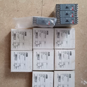
 Contacteur,disjoncteur,onduleur solaire,compteur électrique,batteries solaires

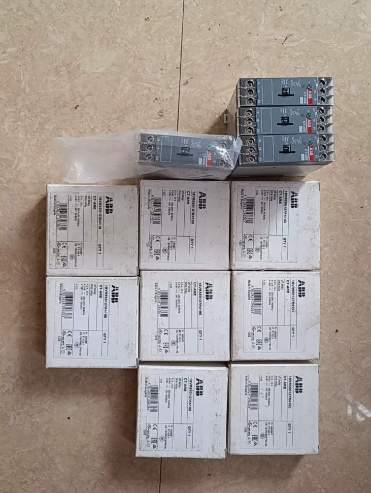

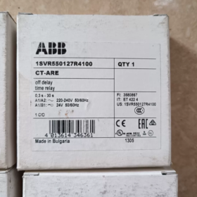
Numéro de commande: 1SVR550127R4100
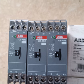
Modèle: CT-ARE
Série de produits: CT-E Economy Single-Function Electronic Time Relay
Type de retard: True OFF-delay (Delay without auxiliary power supply)
Origine: Bulgarie
Type de montage: Standard snap-on mounting for 35 mm rail DIN
Code SH: 85364900
Positionnement de base: Low-cost industrial control power-off sequence control, delay hold for contactors, motors and valves during shutdown
- Breakdown of Order Number 1SVR 550 127 R4100
- 1SVR: General prefix for ABB electronic time relays
- 550: Code for CT-E economy series
- 127: Body code for CT-ARE OFF-delay type
- R4100: Specification suffix
4: Timing range 0.3~30 s
1: Dual-voltage coil (24 V CA/CC + 220~240 V AC)
00: 1 contact inverseur (1c/o SPDT)
III. Core Electrical Specifications
| Élément de paramètre | Valeur de spécification |
| Alimentation de contrôle | A1-A2: 220~240 V AC 50/60 Hz; A1-B1: 24 V CA/CC |
| Plage de retard | 0.3 s ~ 30 s, stepless adjustment via front potentiometer |
| Configuration des contacts | 1 changeover contact 1c/o (SPDT): 15(COM) / 16(NON) / 18(Caroline du Nord) |
| Contacter l'évaluation | AC12 230 V/4 A; AC15 230 V/3 A; DC13 24 V/2 A |
| Précision de répétition | Δt < ±1% under constant operating conditions |
| Temps de réinitialisation | < 50 MS |
| Dielectric Withstand Voltage | 2 kV (between coil and contact circuit) |
| Consommation d'énergie | < 1.8 Virginie |
| Voyant lumineux | 1 LED status indicator (steady on when powered, flashing during delay) |
- Mechanical Dimensions & Conditions environnementales
- Dimensions hors tout: W 22.5 mm × H 78 mm × D 78.5 mm
- Terminaux: Screw-type wiring terminals
- Température de fonctionnement: -20 ℃ ~ +60 ℃; Température de stockage: -40 ℃~+70 ℃
- Classe de protection: IP20 (for internal cabinet installation)
- Poids: Environ. 70 g
- Certifications: CE, CCC, UL/cUL, GL, RoHS; Conforme à la CEI 61812-1
- Principe de fonctionnement (True OFF-delay)
- Coil Energized Stage (Power applied to A1-A2)
Internal timing capacitor charges, contacts act instantaneously: 15-16 fermé, 15-18 ouvrir, LED stays steady on; No timing occurs at this stage.
- Instant Coil De-energization (Power cut triggers delay)
Internal energy storage capacitor independently supplies power for timing without external auxiliary power; LED flashes and contacts remain closed.
- End of Delay Period
Capacitor discharges completely, timing cycle completes, contacts reset: 15-16 opens, 15-18 closes again.
> Key Distinction: Conventional OFF-delay relays require a constant power supply; CT-ARE can complete the full timing cycle after total power cut, ideal for scenarios where the main circuit power supply is fully disconnected.
- Terminal Wiring Definition
A1, A2: Main power supply 220~240 V AC
A1, B1: Auxiliary power supply 24 V CA/CC (select one supply only, do not connect both simultaneously)
15: Common contact terminal COM
16: Normalement ouvert NON (closes when coil energized, remains closed during power-off delay)
18: Normalement fermé NC (closes after coil de-energized and delay expires)
VII. Scénarios d'application typiques
- Delayed heat dissipation after motor shutdown: Fans and water pumps keep running for 0.3~30 s to dissipate heat after main contactor power cut
- Delayed material emptying on conveyor belts: Conveyor runs extra time to clear residual materials after production line shutdown
- Delayed pressure relief for solenoid valves: Cylinders and hydraulic valves maintain pressure for a set time before pressure relief after power-off
- Delayed turn-off of lighting/access control equipment: Work lights and warning lights stay on for a period after equipment shutdown
- Sequence buffer for contactor interlocking: Power-off buffering for high-power equipment switching circuits to prevent short circuits
VIII. Cross Reference of Same Series Models (Direct replacement with identical housing)
| Numéro de commande. | Type de retard | Timing Range | Tension d'alimentation |
| 1SVR550127R1100 | CT-ARE OFF-delay | 0.1~10 s | 24 V CA/CC + 220-240 V et |
| 1SVR550127R4100 (This unit) | CT-ARE OFF-delay | 0.3~30 s | 24 V CA/CC + 220-240 V et |
| 1SVR550107R4100 | CT-ERE ON-delay | 0.3~30 s | 24 V CA/CC + 220-240 V et |
| 1SVR550157R4100 | CT-AWE Pulse OFF-delay | 0.3~30 s | 24 V CA/CC + 220-240 V et |
- Matrice de dépannage
| Phénomène de défaut | Cause première | Solution |
| No contact action and LED off when coil powered | Wrong terminal wiring / missing supply voltage | Check power supply at A1A2/A1B1, distinguish 24 V and 220 V circuits |
| No delay after power cut, contacts reset instantly | Aging or failed internal energy storage capacitor | Replace the whole relay; non-repairable |
| Unstable, inconsistent delay duration | Loose potentiometer or excessive ambient temperature | Retighten potentiometer and install heat dissipation for cabinet |
| Weak contact pull-in, unable to drive load | Contact ablation due to overcurrent | Reduce load power or add intermediate relay for capacity expansion |
| LED does not flash, timing function invalid | Timing circuit damaged by long-term overvoltage | Verify supply voltage range and add voltage stabilization protection |
- Approvisionnement & Notes de sélection
- Portée de la livraison standard: Main unit + DIN rail clip, no base included; direct snap-on mounting to standard 35 mm rail DIN
- Avantage: Wide dual-voltage supply, compatible with both 24 V industrial AC/DC and 220 V mains circuits in one unit
- Restriction: Not suitable for frequent switching cycles (>10 fois par minute), which accelerates capacitor degradation
- Alternative Recommendation: Upgrade to CT-ERS multi-function series if multi-stage delay and multiple contacts are required
Complete Operating Principle of ABB 1SVR550127R4100 (CT-ARE True OFF-Delay Time Relay)
- Core Type Definition
Model CT-ARE is a True OFF-Delay relay, different from conventional OFF-delay relays with auxiliary power supply:
After full power cut of the main circuit, the internal energy storage capacitor provides independent power to complete the timing cycle without continuous external power supply.
The whole device consists of four core parts: power rectifier circuit, energy storage capacitor, timing control chip, driving circuit for 1 contact inverseur, and LED status indicator.
- Full Staged Operating Flow
Scène 1: Coil Energized (Power applied to A1-A2 220~240 V AC / A1-B1 24 V CA/CC)
- External voltage feeds power terminals, internal rectifier and voltage regulator start working;
- One circuit supplies power to the driving coil and contacts act instantaneously:
COM terminal 15 closes with NO terminal 16 and opens NC terminal 18;
- Another circuit continuously fully charges the large-capacity energy storage capacitor;
- Front panel LED remains steady on, no timing is triggered at this stage, contacts stay closed as long as power is maintained.
Scène 2: Instant External Power Cut (Power loss triggers delay)
Power supply at A1/A2 and A1/B1 is completely disconnected with no external input voltage:
- External power circuit is cut off, while energy stored in the internal capacitor discharges to power the timing chip and driving circuit independently;
- LED changes from steady on to flashing to indicate countdown delay in progress;
- Contacts keep the original closed state (15-16 remains closed) without immediate reset;
- The chip counts down uniformly according to the value set by the front potentiometer (0.3 s ~ 30 s).
Scène 3: End of Timing Delay
The energy storage capacitor is fully discharged and the timing cycle finishes:
- Internal drive loses magnetism and changeover contacts reset automatically;
- NO contact 15-16 opens, NC contact 15-18 restores conduction;
- LED turns off and the whole unit stops operation;
- When power is reapplied, the capacitor recharges and waits for the next power-off delay trigger.
III. Exclusive Core Features of True OFF-Delay Type
- No external holding power required
Conventional OFF-delay relays need constant power to maintain the control board and only cut the trigger signal; this unit can complete full timing after total main power cut, suitable for full equipment shutdown and main power disconnection applications.
- Energy storage capacitor serves as timing power source
Capacitor aging directly causes failure: no delay after power cut and instant contact reset; the unit cannot be repaired and must be replaced entirely.
- Potentiometer only adjusts timing threshold
Adjusting the potentiometer while powered does not change the current status; the new setting takes effect only upon the next power-off.
- Terminal Logic Matching Principle
A1, A2: 220~240 V AC main control power supply; energizes to close contacts and charge capacitor;
A1, B1: Wide-range 24 V AC/DC control power supply; select one supply only, do not connect both at the same time;
15(COM), 16(NON): Closed when powered, remains closed throughout power-off delay;
18(Caroline du Nord): Open when powered, closes after delay expires.
- Typical Control Logic Example (Fan Delayed Heat Dissipation)
- Equipment running → Contactor pulls in, CT-ARE energized, fan starts simultaneously;
- Equipment shutdown → Contactor opens, CT-ARE fully de-energized;
- Capacitor supplies power for 30 s delay, fan keeps running for heat dissipation;
- Delay ends, contacts reset and fan stops.
- Core Principle Difference from CT-ERE ON-Delay Relay
- CT-ARE (This unit): Act on power-up, reset with delay after power-off, timing powered by internal capacitor storage;
- CT-ERE (ON-delay): Contacts act after preset time upon power-up, resets instantly after power cut with no energy storage timing circuit.


 Inductive Proximity Sensor")
")


")
NH42-63-318x560.png "Commutateurs de transfert automatiques de type PC CHINT (ATS)NH42-63/4SZ")


