 Contacteur,disjoncteur,capteur,Encodeur,API,Convertisseur

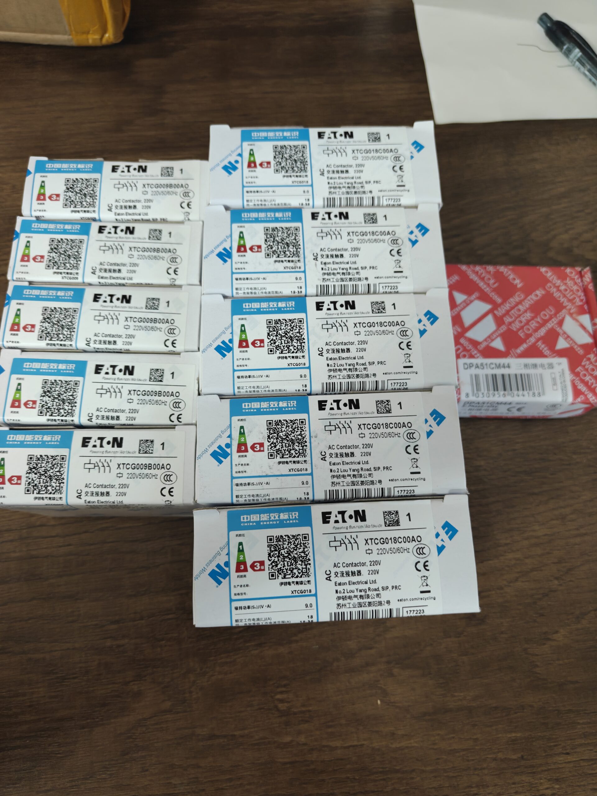

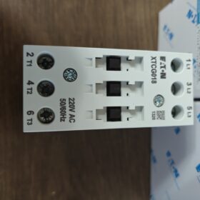
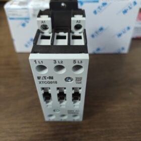
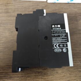
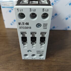
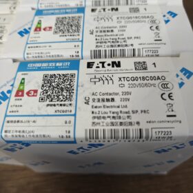
Note: Le dernier caractère est la lettre O, pas de chiffre 0; appartient à la sous-série XTCG de la gamme IEC Eaton XT contacteurs.
Décodage du code modèle
| Segment de code | Description |
| XT | Eaton Série de commandes CEI de la gamme XT |
| C | Contacteur |
| G | Série XTCG, Contacteur moteur tripolaire à vis |
| 18 | Courant de fonctionnement nominal AC‑3:18A pour circuit principal |
| C | Taille de cadre C, 45 boîtier de largeur mm |
| 0 | Pas de contacts auxiliaires intégrés (0NON+0NC) |
| AU | Bobine: AC220V 50/60Hz (A = CA, O=code pour bobine 220VAC) |
Définition complète: 3-pôle, AC-3 18A, pas de contacts auxiliaires intégrés, Bobine AC220V, contacteur AC à borne à vis.
Paramètres électriques de base
| Article | Spécification |
| Pôles principaux | 3P‑NON (trois contacts principaux normalement ouverts) |
| Courant de fonctionnement nominal AC‑3 | 18Une charge moteur à 400 V |
| Charge résistive AC‑1 | 32UN |
| Tension d'isolement nominale Ui | 690V |
| Tension de bobine | AC220V 50/60Hz |
| Contacts auxiliaires | Aucun à bord; accessoires externes XTCGXF*** requis |
| Endurance mécanique | ≥10000000 opérations |
| Endurance électrique AC‑3 | ≥1 000 000 opérations |
| Montage | Montage sur rail DIN35 ou montage sur plaque arrière à visser |
| Terminaux | Bornes à vis-étrier |
| Certifications | CCC, CE, UL, ASC, CEI60947‑4‑1 |
Physique & Conditions environnementales
Largeur du boîtier: 45 mm
Température de fonctionnement:-25℃ ~ +60℃, condensation et givrage interdits
Température de stockage:-40℃ ~ +85℃
Poids: environ. 0.21 kilos
Scénarios d'application typiques
- Commande démarrage/arrêt de moteur triphasé (Moteur ≤7,5 kW à 400 V)
- Ventilateurs, pompes à eau, convoyeurs, compresseurs d'air, machines d'emballage
- CVC & assemblage OEM d'armoire; peut être associé au relais de surcharge thermique XTOD pour la protection contre les surcharges du moteur
Liste des accessoires compatibles
Bloc de contacts auxiliaires: XTCGXFAC (1NON+1NC etc.), monté sur le côté
Relais de surcharge thermique: XTOD018 (0.1-18Une couverture protection moteur)
Module de verrouillage mécanique: XTCG-MV, pour circuit inverseur
Suppresseur de surtension: RC / module varistance côté bobine
Modèles de remplacement direct & Notes de remplacement
- Alternative de même série: XTCG018C00DT (code de bobine différent; vérifier la tension de la bobine, pas un remplacement immédiat)
- Alternative inter-séries: XTCE018C00A0 (Série Eaton XTCE, fonctionnellement équivalent; vérifier la compatibilité des accessoires)
⚠️Rappel des pièges: XTCG018C00AO n'a pas de contacts auxiliaires intégrés. Un accessoire de contact auxiliaire externe doit être installé si des signaux de retour PLC sont requis, sinon les circuits de commande ne peuvent pas fonctionner.
Conditions de fonctionnement non applicables
Fréquence de commutation > 1 200 cycles/heure
Gaz corrosif lourd / environnement très poussiéreux sans protection adéquate
Applications de bobines CC (cette unité est de type bobine AC)
Brèves instructions de câblage
- Circuit principal: Côté alimentation L1-L2-L3; Charge T1-T2-T3 (moteur) côté
- Les bornes de bobine A1/A2 se connectent à AC220V
- Pas de contacts auxiliaires intégrés; tous les signaux de retour logique doivent être obtenus à partir d'accessoires de contact auxiliaire installés à l'extérieur.
XTCG018C00AO (Cadre C) Montage & Dimensions hors tout (Unité: mm)
Tous les modèles de cadre XTCG-C (009-032UN) partagent des dimensions de logement identiques. Prend en charge le montage sur rail DIN35 ET le montage sur plaque arrière à visser.
Dimensions hors tout (sans accessoires montés)
| Article | Valeur | Remarques |
| Largeur W | 45 | Référence pour l'espacement des armoires |
| Hauteur H | 85 | Hauteur totale incluant le haut & bornes inférieures |
| Profondeur D | 97.4 | Profondeur à l'intérieur du panneau de l'armoire après montage sur rail |
Dimension hors tout: 45(W) × 85(H) × 97.4(D) mm
Dimensions de découpe de la plaque arrière à visser (Rail DIN oublié, fixation par vis directe sur la plaque arrière du meuble)
Espacement centre à centre des trous de montage horizontaux: 35 mm
Espacement centre à centre des trous de montage verticaux: 76 mm
Diamètre du trou de fixation: Φ4,5 (Vis M4)
Marge du trou au bord: environ 4,5 mm en haut & bas.
Informations sur l'installation sur rail DIN
- Rail standard DIN-35-7,5 (rail électrique universel de 35 mm)
- Clip encliquetable à l'arrière pour un montage direct sur clip de rail; assemblage sans outil & démontage.
⚠️Changement de dimension après l'installation des accessoires
- Bloc de contacts auxiliaires à montage latéral XTCGXF: la largeur augmente de 10 mm, largeur totale 55mm
- Relais de surcharge thermique à montage inférieur XTOD: la hauteur totale augmente d'environ 42,5 mm
- Verrouillage mécanique XTCG-MV: deux contacteurs côte à côte sans écart nul; largeur totale = somme directe (45+45=90mm)
Conditions limites d’installation
- Jeu de refroidissement: ≥10 mm en haut & bas; pas de dégagement obligatoire côte à côte (plusieurs unités peuvent être montées adjacentes les unes aux autres)
- Ne pas monter fermement contre des cloisons d'armoire fermées; température ambiante-25 ℃ ~ + 60 ℃, condensation interdite.
- Taille de conducteur maximale autorisée: circuit principal 6mm²; circuit bobine 2,5mm².
Référence inter-modèles
Modèles XTCG009C / XTCG025C / XTCG032C partage un boîtier identique, dimensions de découpe et de montage sur rail; seul le courant nominal du contact interne diffère. Codes de tension de bobine variés (AO/DT, etc.) ne produit aucun changement dans les dimensions physiques.
Différenciation de tension de fonctionnement pour Eaton XTCG018C00AO
Deux systèmes de tension distincts existent pour les contacteurs: circuit principal (principaux interlocuteurs) et circuit de commande de bobine. Ne les confondez pas.
- Tension de commande de bobine (code suffixe AO)
Tension nominale de la bobine: CA 220 V 50/60 Hz
Terminaux: A1, A2
Plage de tension de fonctionnement admissible de la bobine: 0.85~1,1×Ue, c'est à dire. AC187V ~ AC242V
⚠️Il s'agit d'une bobine AC. L'alimentation CC est strictement interdite.
- Circuit principal (contacts principaux pour les charges du moteur)
| Paramètre | Valeur |
| Tension assignée d'emploi Ue | Max.. AC690V |
| Tensions de fonctionnement communes | AC230V / 400V / 500V / 690V |
| Tension assignée d'isolement Ui | 690V |
| Tension de tenue aux chocs Uimp | 6 kV |
La valeur nominale 18 A AC-3 est spécifiée à 400 V. Le circuit principal peut fonctionner entre 0 et 690 V CA.; le courant admissible varie en fonction de la tension appliquée.
Notes complémentaires clés
- Le suffixe « AO » désigne exclusivement la bobine AC220V. Changer le code suffixe (par exemple. DT=AC380V) modifie uniquement la tension de la bobine; la capacité de tension du circuit principal reste inchangée.
- Une tension en dehors de la plage de fonctionnement autorisée de la bobine provoque des défauts: sous-tension → échec d'extraction / bavarder; surtension → surchauffe de la bobine & épuisement professionnel.
- Le déclassement du courant du circuit principal s'applique à des températures ambiantes élevées.
Guide de dépannage de la bobine XTCG018C00AO
Spécification de la bobine: AC220V 50/60Hz; Bornes A1/A2; plage de fonctionnement autorisée AC187V-242V; Alimentation DC interdite.
Faute 1: Le contacteur ne s'enclenche pas du tout, réponse acoustique nulle
Causes profondes probables
- Pas de tension sur le circuit de commande: 0V mesuré sur A1/A2; relais amont / Sortie API / fusible / fil cassé / borne lâche.
- Tension d'alimentation de la bobine inférieure à 0,85Ue (<187V): tension insuffisante pour le pull-in.
- Grillage en circuit ouvert de la bobine: lecture de résistance infinie entre A1-A2 via un multimètre.
- Saisie mécanique: pénétration de corps étrangers, noyau de fer corrodé, accessoires supplémentaires mal installés provoquant un blocage mécanique.
Étapes correctives
- Confirmation de sécurité de mise hors tension; mesurer la tension sous tension aux bornes A1/A2.
- Mise hors tension; débrancher le câblage de la bobine; mesurer la résistance CC de la bobine autonome. Résistance typique de la bobine AC220V à cadre C: 1300-1500 Oh. Résistance infinie = bobine brûlée; résistance proche de zéro = bobine en court-circuit.
- Actionner manuellement l'induit du contacteur; vérifier la fluidité du mouvement. Si vous collez, enlever les débris étrangers; inspecter l'ajustement du contact auxiliaire / accessoires de verrouillage.
- Vérifier la continuité du fusible du circuit de commande, Sorties API et relais intermédiaires.
Faute 2: Le contacteur bavarde / fort bourdonnement, entrée instable
Causes profondes probables
- Tension de bobine faible et marginale; à long terme / un câblage de commande de faible épaisseur crée une chute de tension excessive.
- Surfaces de contact des noyaux de fer contaminées par de l'huile, poussière ou particules de fer; entrefer magnétique élargi.
- Distorsion de la forme d'onde d'alimentation, distorsion harmonique causée par les interférences VFD.
- Bobine dégradée avec court-circuit partiel entre spires.
Étapes correctives
- Mesure en direct de la tension A1/A2; doit rester dans AC187-242V. Augmentez la section transversale du câble de commande pour les boucles de commande longue distance.
- Mise hors tension; nettoyer les surfaces de contact du noyau de fer de la poussière de fer et des débris. Ne PAS appliquer de graisse ou d'huile lubrifiante.
- Mesurer la résistance de la bobine; une résistance nettement inférieure à la valeur nominale indique un court-circuit entre spires; remplacer l'unité de contacteur complète.
- Installer un suppresseur de surtension de bobine de type RC en cas d'interférences électromagnétiques graves.
Défaut3: Surchauffe persistante de la bobine / épuisement rapide
Causes profondes probables
- Mauvaise tension d'alimentation: AC380V appliqué à une bobine AC220V - cause d'épuisement la plus fréquente.
- Tension d'alimentation continue > 1,1 Ue (>242V), fonctionnement à long terme en cas de surtension.
- Le blocage mécanique empêche la fermeture complète de l'armature; un grand entrefer résiduel maintient le courant de bobine élevé en permanence.
- Alimentation CC accidentelle à la bobine CA: épuisement instantané.
Étapes correctives
- Vérifiez à nouveau la tension d'alimentation réelle; correspondre strictement à la valeur nominale de la bobine AC220V codée AO.
- Vérifier le libre mouvement mécanique; confirmer la fermeture complète de l'armature.
- Confirmer l'alimentation CA uniquement; ne conduisez jamais avec une source DC.
Bobine grillée: Les bobines de la série XTCG ne sont pas remplaçables individuellement sur site. Remplacer l'ensemble complet du contacteur.
Défaut4: Le contacteur ne parvient pas à se libérer après la mise hors tension (coincé fermé)
Distinguer le soudage au contact principal de la tension résiduelle de la bobine / anti-grippage mécanique.
- La tension résiduelle persiste aux bornes de A1/A2 après la mise hors tension de la bobine (Courant de fuite API, tension résiduelle des voyants parallèles).
- Saisie mécanique; fatigue du ressort de rappel.
- Événement de court-circuit du circuit principal entraînant des contacts principaux soudés.
Étapes correctives
- Mesurer la tension résiduelle aux bornes A1/A2 hors tension. Résiduel > 30 V empêche la libération; Ajuster l'amortisseur RC pour la dissipation de tension.
- Débranchez l'alimentation du circuit principal; tester l'action de retour manuelle du mécanisme. Remplacez l'unité en cas de défaillance du ressort..
- Inspecter les contacts principaux pour le soudage par brûlage. Les contacts soudés nécessitent un remplacement complet de l'unité; ne pas remettre à neuf en polissant les contacts pour un service continu.
⚠️Opérations strictement interdites
- N'appliquez jamais de tension CC à la bobine CA 220 V CA.; risque d'épuisement instantané.
- Ne court-circuitez pas les bornes A1/A2 à des fins de test.
- Ne pas appliquer de puissance à plusieurs reprises sur une bobine déjà brûlée; risque secondaire de dommages à l'armoire.
- Ne jamais appliquer d'huile / graisser sur les surfaces de contact des noyaux de fer; l'huile emprisonne la poussière ferreuse et provoque un bourdonnement / échec de fermeture bloquée.
Matrice de test de référence rapide
| Élément de mesure | Valeur de référence acceptable | Jugement de faute |
| Tension de fonctionnement de la bobine sous tension | CA 187‑242 V | <187V: échec d'extraction;>242V: épuisement professionnel par surchauffe |
| Résistance CC de la bobine(A1-A2) | 1300‑1500Ω | Infini = circuit ouvert; lecture beaucoup plus basse = court-circuit tour à tour |
| Tension résiduelle A1‑A2 (mise hors tension) | <10V | >30 V risque d'échec de libération |
Note complémentaire: Aucun contact auxiliaire intégré. Le bloc de contacts auxiliaires externe à montage latéral XTCGXF est obligatoire pour les signaux de retour d'état.








NH42-63-318x560.png "Commutateurs de transfert automatiques de type PC CHINT (ATS)NH42-63/4SZ")



