 Contacteur,disjoncteur,capteur,Encodeur,API,Convertisseur

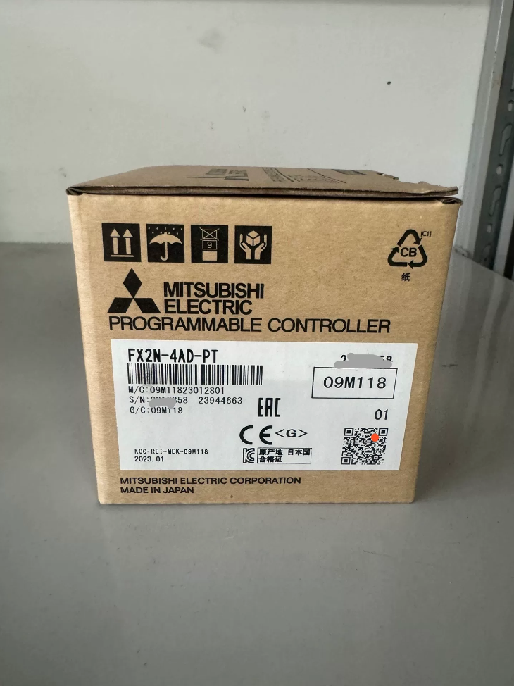
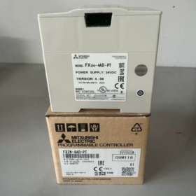
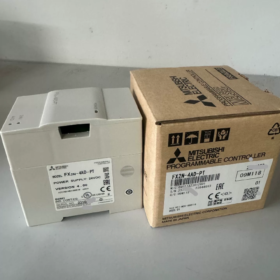
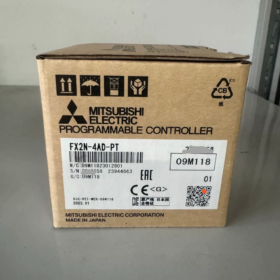
Module d'extension spécial pour API série FX, conçu pour l'acquisition de température à résistance platine PT100 à 4 canaux et 3 fils. Obsolète (abandonné). La communication est implémentée via les instructions de registre de mémoire tampon FROM/TO. 2Les capteurs PT100 à fil ne sont pas pris en charge.
- Décomposition du code modèle
| Segment | Description |
| FX2N | Série API, Module d'extension FX2N |
| 4ANNONCE | 4entrée analogique à 1 canal |
| ‑PT | Module RTD spécial pour résistance platine PT100; il ne s'agit pas d'un module AD tension/courant à usage général |
- Électricité de base & Spécifications techniques
| Article | Spécification |
| Capteur pris en charge | 3‑fil PT100 (100 Oh); le module fournit une excitation à courant constant de 1 mA au capteur |
| Plage de température | -100 ℃ ~ +600 ℃; Fahrenheit: -148 ℉ ~ +1 112 ℉ |
| Format de sortie numérique | mode ℃: valeur = température ×10 (par exemple. 25.0 ℃ → 250); Mode ℉: valeur = ℉ ×10 |
| Résolution | 0.2~0,3℃ / 0.36~0,54 ℉ |
| Précision | ±1 % de la plage pleine échelle |
| Temps de conversion | 15 mme pour tous 4 chaînes |
| Résolution AD | 12-peu (y compris le bit de signe) |
| Alimentation côté API | 5 V CC tiré du bus d'extension API, consommation 30mA; externe 24 V CC pour circuit analogique du module |
| Points d'E/S occupés | 8 points (entrée ou sortie, aucun terminal physique occupé) |
| Isolement | Isolation par optocoupleur entre circuits analogiques et numériques; pas d'isolation entre les canaux |
| Poids | Environ. 0.3 kilos; Montage sur rail DIN |
| Code d'identification BFM#30 | K2040; lu par programme pour vérifier la présence du module |
| Processeurs API compatibles | FX0N/FX1N/FX2N/FX2NC/FX3G/FX3U/FX3UC; Non compatible avec FX5U |
⚠️ Restriction dure: 2‑wire PT100 n’est pas pris en charge. La connexion forcée de capteurs à 2 fils entraînera une dérive de température importante et des mesures inexactes. Seul le RTD à 3 fils est autorisé.
- Mémoire tampon de clé (BFM) Liste (DE = Lire / À = écrire)
| BFM | R/É | Description de la fonction |
| #0 | W | Norme PT100: K0 = JIS C1604‑1997 (DIN3850); K1 = héritage JIS C1604‑1981 |
| #1~#4 | W | Calcul de la moyenne du nombre d'échantillons pour CH1‑CH4, plage 1 à 4096, par défaut = 8; valeur plus élevée = filtrage plus fort, réponse plus lente |
| #5~#8 | R. | Température moyenne en ℃ pour CH1‑CH4 (×10); couramment utilisé en ingénierie |
| #9~#12 | R. | Température actuelle instantanée en ℃ pour CH1‑CH4 (×10) |
| #13~#16 | R. | Température moyenne en ℉ pour CH1‑CH4 (×10) |
| #17~#20 | R. | Température actuelle instantanée en ℉ pour CH1‑CH4 (×10) |
| #21 | W | Écrivez K1 pour restaurer l'étalonnage d'usine; inscription effacée automatiquement par la suite |
| #28 | R. | Verrouillage d'erreur de canal (rupture de fil, verrou hors de portée) |
| #29 | R. | Registre des états d'erreur (critique); drapeaux d'alarme basés sur les bits |
| #30 | R. | Code d'identification du module K2040 pour la validation du module côté programme |
Définition des bits de BFM29 pour le dépannage
| Peu | Description du défaut | Remède |
| b0 | Paramétrage incorrect dans BFM#0 | Réglez BFM#0 sur K0 ou K1 |
| b1 | Compte de moyenne n°1 à n°4 sur la plage de 1 à 4 096 | Modifier la valeur moyenne de l'échantillon |
| b2 | Défaut matériel, anomalie du module | Remplacer le module |
| b10 | Valeur numérique hors plage (rupture de fil du capteur / dépassement de température) | Vérifiez le câblage du PT100; vérifier le capteur grillé |
- Directives de câblage
- 3‑le fil PT100 est obligatoire. Trois conducteurs doivent avoir autant que possible une résistance et une section égales.
- Utilisez des câbles à paires torsadées blindées pour le câblage du signal RTD.; acheminer séparément des câbles haute puissance pour réduire les interférences.
- Module d'alimentation avec 24 V DC; mettre à la terre de manière fiable le terminal FG.
- N'appliquez jamais de signaux de tension aux bornes PT, sinon, des dommages permanents au module se produiront.
- Attribution du numéro de module: Le premier module spécial adjacent au CPU est le module n°.0, comptant vers la droite comme n°1, N°2, N°3. Le premier opérande de FROM/TO est le numéro de module.
Exemple de logique à relais simple (Numéro de module.0, lire la valeur ℃ moyenne de CH1 dans D0)
DE K0 K5 D0 K1
D0 = température moyenne CH1 ×10; par exemple. D0 = 250 équivaut à la température réelle 25,0 ℃.
- Remplacement de produits abandonnés & Options de mise à niveau
FX2N‑4AD‑PT est obsolète. Solutions regroupées par plateforme CPL.
1) Conserver la plateforme de la famille FX FX3U/FX3UC
- FX3U‑4AD‑PT: Remplacement direct du matériel, 4‑canal PT100, compatible avec les fonctions, Communication DEPUIS-À inchangée; adaptation mineure du programme requise.
Note: Le FX3U‑4AD‑PT est également progressivement supprimé.
2) Mise à niveau vers la plateforme FX5U
FX5‑4AD‑PT: Module de température RTD dédié au CPU FX5U.
Schéma alternatif: Module d'entrée analogique général plus transmetteur RTD externe.
Remplacement compatible tiers
Unité compatible domestique: TX2N‑4AD‑PT. Compatible avec les broches du bus d'extension FX2N; mappage de registre identique, permet un échange direct de matériel.
- Pièges de sélection & Conditions non applicables
- ❌ Les capteurs PT100 à 2 fils ne peuvent pas être utilisés.
- ❌ Pas pour les entrées thermocouple (utiliser FX2N‑4AD‑TC pour les thermocouples de type K/J; Les modules PT et TC ne sont pas interchangeables).
- ❌ Pas d'isolation intercanal. La différence de potentiel de mode commun entre plusieurs points de mesure introduit des interférences; isolation externe requise.
- ✅ Applications typiques: Fours, systèmes de traitement de l'eau, barils de machines de moulage par injection, stockage au froid et autres mesures de température industrielle entre -100 et 600 ℃.
- Environnements à fortes interférences: Augmenter le nombre moyen d’échantillons dans BFM1‑4 (réglé sur 16‑32) pour le filtrage numérique.
- Diagnostic de panne courant
- Lecture fixe à -1000 (-100 ℃) ou 6000 (600 ℃): Très probablement rupture de fil PT100 ou mauvais câblage à 3 fils. Vérifiez si BFM29 b10 est activé.
- Forte dérive de température: Vérifiez la résistance égale des trois fils du capteur; vérifier la mise à la terre du blindage; tenir à l'écart des câbles d'alimentation.
- Toutes les valeurs sont lues à zéro via l'instruction FROM: Mauvais numéro de module; Alimentation du bus 5 V insuffisante. Lire le code d'identification BFM30 pour confirmer la communication.
- Forte fluctuation des lectures: Augmenter le nombre moyen d’échantillons dans BFM1‑4.
Rappel de distinction de module: FX2N‑4AD‑PT pour PT100 RTD vs FX2N‑4AD‑TC pour thermocouples K/J. Le matériel ne peut pas être échangé.
Cas d'application du FX2N‑4AD‑PT dans le domaine industriel
Caractéristiques des modules: 4Acquisition RTD PT100 à 3 canaux à 3 fils, abandonné. Échange de données via les instructions FROM‑TO BFM. Convient à la surveillance multipoint de la température, gestion des alarmes et contrôle de température en boucle fermée PID pour les équipements de petite et moyenne taille. Ci-dessous quatre cas pratiques industriels, y compris la configuration matérielle, affectation des points de mesure, logique de processus, extraits clés du programme, notes de mise en service et avertissements de risques sur site.
Cas 1: Surveillance multipoint de la température pour les petits entrepôts frigorifiques / Refroidisseur (Industrie du froid)
Matériel système
API: FX2N‑32MR; Module spécial: FX2N‑4AD‑PT (Numéro de module.0)
Capteurs: 4 morceaux de PT100 à 3 fils de classe A
Affectation des points de mesure
CH1: Température ambiante de stockage au froid
CH2: Température des gaz de retour de l'évaporateur
CH3: Température de l'eau à la sortie du condenseur
CH4: Température de sortie d'eau glacée
Actionneurs: 2 compresseurs, ventilateur du condenseur, alarme sonore et visuelle; affichage de la température via l'écran tactile HMI
Exigences du processus
- Lorsque la température de stockage> 10 ℃: Compresseur 1 commence; température> 12 ℃: Compresseur 1 + 2 courir simultanément.
- Quand la température descend à 6℃: Arrêter le compresseur 1; la température descend à 3℃: Arrêtez les deux compresseurs.
- Alarme déclenchée pour une température <‑2 ℃ (température ultra basse); La rupture de fil du capteur déclenche un verrouillage en cas de panne pour interdire le démarrage du compresseur.
- Toutes les valeurs de température téléchargées sur HMI; journalisation des événements de dépassement de limite activée.
Configuration des clés
- BFM0 = K0 (Norme DIN PT100); BFM1‑4 = K16 (16-moyenne d'échantillon pour supprimer les interférences de champ à l'intérieur de l'entrepôt frigorifique).
- Lire la température moyenne de 4 chaînes de BFM5~8 (valeur brute = température ×10).
- Lire BFM29 pour la détection de rupture de fil et de défaut matériel; verrouillage de l'arrêt du compresseur en cas de panne pour assurer la protection de l'équipement.
Extrait de clé (Échelle de développement GX)
M8002 // Impulsion d'initialisation
DE K0 K30 D10 K1 // Lire le code d'identification du module
CMP K2040 D10 M0 // Comparez pour valider FX2N‑4AD‑PT
M8000
DE K0 K5 D0 K4 // Lire la température moyenne CH1‑CH4 dans D0‑D3
DE K0 K29 K4M10 K1 // Mapper les bits d'état d'erreur sur M10‑M25
Divisez D0 par 10 pour obtenir la température de stockage réelle; utiliser l'instruction de comparaison de zones ZCP pour la logique de seuil de démarrage et d'arrêt du compresseur.
Risques sur site
L’environnement d’entreposage frigorifique est humide; garder les borniers PT100 étanches à l'humidité. 2‑fil PT100 strictement interdit en raison de fortes dérives. Pas d'isolation canal à canal; appliquer une mise à la terre du blindage en un seul point lorsque plusieurs sondes partagent une masse de référence.
Cas 2: Contrôle de la température pour le réservoir de pasteurisation des aliments (Industrie agroalimentaire)
Configuration matérielle
Automate FX2N‑64MR; FX2N‑4AD‑PT (Numéro de module.0); Module de sortie analogique FX2N‑4DA
3 morceaux de PT100 à 3 fils:
CH1: Température du matériau à l'intérieur du réservoir (Retour de contrôle principal PID)
CH2: Température de l'eau à l'entrée de l'échangeur thermique
CH3: Température de l'orifice de décharge
CH4: Canal de rechange
Actionneurs: Relais statique SSR pour chauffage électrique; pompe de circulation; vanne de dérivation de décharge; PID en boucle fermée via l'instruction FNC88.
Exigences du processus
- Chauffer le matériau jusqu'à 92 ℃ et maintenir pendant 15 secondes. Ouvrir la vanne de décharge une fois le point de consigne atteint; détourner les matériaux non qualifiés pour les recycler.
- Décharge interdite lorsque la température est inférieure à 85 ℃. Couper immédiatement la puissance de chauffage, déclencher une alarme et un système d'arrêt sur la rupture de fil PT100 pour éviter tout risque de brûlure à sec.
- L'IHM affiche trois relevés de température; enregistrement des données de processus pour répondre aux exigences de conformité HACCP.
Points saillants du programme
- D0 (Lecture CH1) sert de PID PV (variable de processus, valeur brute ×10); consigne SV = 920 représentant 92,0 ℃.
- Sortie PID envoyée au FX2N‑4DA, générer un signal analogique 0-10 V pour piloter la régulation de puissance SSR.
- Quand BFM29 b10 (drapeau de rupture de fil) est allumé: réinitialiser la sortie PID et la sortie de chauffage forcée Y0.
Notes de mise en service
La boucle de chauffage présente une grande inertie thermique & décalage; régler les paramètres P/I/D PID de manière itérative. Augmentez le nombre de moyennes BFM1 pour atténuer le bruit de champ causé par le moteur.
Cas 3: Mesure de température multipoint pour étuve de séchage dans l'emballage & Machines d'impression
Matériel
FX2N‑48MR + FX2N‑4AD‑PT
CH1: Température d'entrée du four
CH2: Partie médiane du four (point principal de contrôle du processus)
CH3: Température de sortie du four
CH4: Température de l'air évacué
Actionneurs: Éléments chauffants commandés par contacteur; verrouillage du ventilateur; coupure du chauffage en cas de surchauffe.
Logique du processus
- Contrôle de température constante avec point de consigne réglable de 80 à 130 ℃, prendre la température CH2 à mi-four comme retour principal.
- Déclenchez le verrouillage en cas de surchauffe et coupez toute puissance de chauffage si la température de sortie est supérieure à 150 ℃.; activation du chauffage interdite si ventilateur en panne.
- Téléchargez quatre points de température sur l'IHM et enregistrez les événements de surchauffe.
Notes d'ingénierie
Température ambiante élevée autour du four; déployer des câbles blindés résistant aux hautes températures pour les capteurs PT100. Séparez les câbles de signal des câbles d'alimentation avec un dégagement minimum ≥20 cm. Installer le filtre sur l'alimentation 24V du module.
>⚠️ Ne s'applique pas aux températures supérieures à 600 ℃ (limite supérieure de la plage de mesure du module). Utilisez plutôt le module thermocouple FX2N‑4AD‑TC pour les applications à température plus élevée.
Cas 4: Surveillance de la température pour les petits réacteurs à agitation chimique (Industrie de la chimie fine)
Configuration matérielle
FX2N‑48MR, FX2N‑4AD‑PT; 4PT100 à 3 fils à canaux
CH1: Température du matériau à l'intérieur du réacteur (contrôle principal)
CH2: Température du fluide chauffant de la chemise
CH3: Température de sortie de l'eau de refroidissement
CH4: Température de la paroi extérieure du réacteur
Sorties: Électrovanne de chauffage, électrovanne d'eau de refroidissement, moteur d'agitateur, sortie d'alarme.
Logique du processus
- Ouvrir la vanne de chauffage pendant la phase de chauffage; fermer le chauffage une fois la température cible atteinte; vanne d'eau de refroidissement à ouverture automatique pour une protection contre la surchauffe.
- Le système entre dans un état sûr en cas de rupture de fil du capteur: fermer la vanne de chauffage, eau de refroidissement ouverte, activer l'alarme sonore et visuelle.
- Comparaison de température multicanal pour alarme en cas de différence de température excessive entre l'intérieur du réacteur et l'enveloppe, pour éviter une surchauffe locale.
Considérations sur les risques
Atmosphère corrosive à l’intérieur d’une usine chimique; adopter des manchons de protection anticorrosion pour les sondes PT100. Pas d'isolation intercanal; fluctuation de lecture potentielle causée par le décalage de potentiel de terre entre les points de mesure; mettre en œuvre une mise à la terre à une extrémité du côté du capteur.
Règles générales de mise en œuvre de l'ingénierie (Commun dans quatre cas)
- Vérification du numéro de module: Le premier module spécial adjacent au CPU = K0, incrémenter vers la droite jusqu'à K1/K2. Le premier opérande de FROM/TO doit correspondre au numéro de module physique. Lire BFM30 = K2040 pour valider la configuration matérielle.
- Discipline du câblage: Utilisez uniquement des capteurs PT100 à 3 fils. Faire correspondre la résistance à trois fils; mise à la terre en un seul point pour le blindage; interdire strictement l'injection de tension dans les bornes du capteur.
- Modèle de gestion des pannes: Lire BFM29 à chaque cycle de balayage. b10 ON indique une rupture de fil de canal. Le programme doit mettre en œuvre un verrouillage de sécurité plutôt qu'une alarme uniquement.; réduire la puissance de chauffage pour éviter les accidents.
- Conversion de lecture: Valeur brute du registre = température réelle ×10; par exemple. `D0=250 →25,0℃`.
- Directive de mise à niveau abandonnée: Pour le système FX2N existant migrant vers FX3U: sélectionnez FX3U‑4AD‑PT. Pour la migration FX5U: adopter FX5‑4AD‑PT.



NH42-63-318x560.png "Commutateurs de transfert automatiques de type PC CHINT (ATS)NH42-63/4SZ")



