 Contacteur,disjoncteur,capteur,Encodeur,API,Convertisseur


✅ Model Interpretation
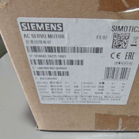
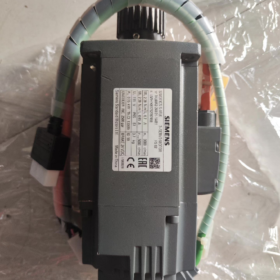
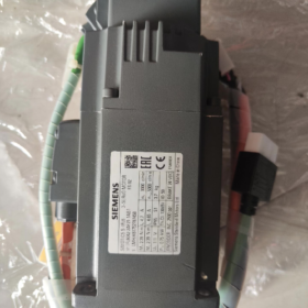
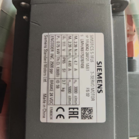
1FL6042-2AF21-1AB1
1FL6: SIMOTICS S-1FL6 V90 servomoteur série
042: Frame size SH40, 0.75kW
2: Faible inertie (LI)
UN: AC230V single-phase / triphasé
F21: Incremental TTL encoder, 2500ppr, sortie de câble
1: Montage sur bride B5
UN: With parallel key; B: Avec frein électromagnétique
Référence: 1AA1 = Same specification without brake
📋 Core Technical Specifications
| Article | Paramètre |
| Puissance nominale | 0.75 kW (750W) |
| Vitesse nominale | 3000 tr/min |
| Couple nominal | 2.39 N·m |
| Maximum Torque | 7.2 N·m (3x surcharge) |
| Courant nominal | 4.7 UN |
| Classe de tension | C.A. 230 V (1CA / 3CA) |
| Encodeur | Incremental TTL, 2500 ppr |
| Inertia Type | Faible inertie (LI) |
| Shaft Extension | Parallel key shaft, N tolerance class |
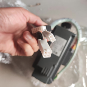
| Frein | Built-in electromagnetic brake (power-off holding brake) |
| Classe de protection | IP65 (with shaft oil seal) |
| Méthode de refroidissement | Refroidissement naturel |
| Classe d'isolation | Classe B (130℃) |
| Frame Height | SH40 |
| Poids net | Environ. 2.8kilos (slightly heavier for brake version) |
| Lecteur compatible | SINAMICS V90 (230Version V: Impulsion / PN communication type) |
| Code SH | 85015100 |
🛠️ Application Scenarios
Faible inertie & réponse dynamique élevée, suitable for short-cycle positioning:
Machines CMS, distributeurs automatiques, small gantries
Équipement d'emballage, handling manipulators, conveyor positioning
Machine tool feed axes, outillage d'inspection
📌 Matching Components for Selection
- Recommended drives: 6SL3210-5FB10-8UA0 (Type d'impulsion) / 6SL3210-5FB10-8UF0 (PN PROFINET)
- Câble d'alimentation: par exemple. 6FX3002-5CK01-1AD0
- Encoder cable: par exemple. 6FX3002-2DB10-1AD0
⚠️ Installation & Notes d'entretien
- Température ambiante: 0~40℃ without derating; max relative humidity ≤90%, pas de condensation
- Frein: Power-off holding brake, released when powered on. The brake cannot be used for dynamic braking during operation, only for holding at standstill.
- IP65: Motor body dust-tight and splash-proof; cable connectors must be tightly fastened. Not suitable for long-term immersion.
- Montage: IM B5 flange, horizontal or vertical installation. Reserve sufficient brake load margin for vertical mounting.
- Key inspection points for used motors: Encoder waveform, brake pull-in/release performance, 3-phase winding balance, résistance d'isolement, bearing noise.
🔁 Alternative Models in the Same Series
1FL6042-2AF21-1AA1: Same parameters, sans frein
1FL6042-2AF21-1MB1: Codeur absolu monotour, avec frein
1FL6042-2AF21-1MA1: Codeur absolu monotour, sans frein
Shaft Parameters of Siemens 1FL6042-2AF21-1AB1
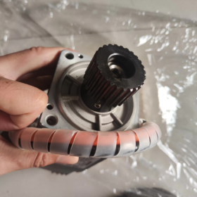
Diamètre de l'arbre: Φ10 mm, with parallel keyway, shaft tolerance N
Parallel key dimension: 3×3×16 mm
Shaft extension length: 22 mm
Bride: B5, frame height 40mm (SH40)
Troubleshooting Checklist for Siemens 1FL6042-2AF21-1AB1 (V90 0.75kW with Brake)
Précaution de sécurité: Power off and wait 5 minutes for DC bus discharge before plugging/unplugging cables. High voltage hazard. Apply mechanical protection during loaded tests. This motor uses a power-off holding brake. Forcing enable with brake locked will trigger stall alarm directly.
- Visual & Inspection mécanique (Power OFF, Priorité)
- Motor housing: Check for cracks, water/oil contamination, terminal box corrosion, bent/pushed-out pins or oxidation on connectors.
- Câbles: Pouvoir & encoder cables for damaged jacket, sharp bending, bornes desserrées. Separate routing for power and encoder cables; 360° shielding grounding.
- Brake Inspection (Critical for this model)
Apply DC24V to brake terminals individually and verify pull-in/release sound. Brake locks when power removed.
After brake release, manually turn shaft: smooth rotation without sticking or friction noise. If still locked → brake mechanical seizure or coil damage.
Measure brake coil resistance: Normal value in tens of ohms. Open circuit = broken coil; near 0Ω = shorted coil.
❗ Brake is not for dynamic braking during operation; only standstill holding.
- Bearing check: Manually rotate shaft, listen for rustling, squealing or metal friction noise. Check excessive radial/axial play or jerky rotation.
- Couplage & charger: Disconnect load and test motor standalone, to distinguish motor failure from mechanical jamming / désalignement.
- Mesure électrique statique (Power OFF, disconnect all cables from drive side)
Test object: Corps du moteur, all cables disconnected
- DC resistance of 3-phase windings (measure U/V/W pairwise)
Acceptance: Resistance deviation between 3 phases <5%, faible résistance (milliohm range)
Anomalie: Infinite resistance on one phase = broken winding; unbalanced/lower resistance = inter-turn short; near 0Ω = phase-to-phase short.
- Résistance d'isolation (500V megger)
Measure U, V, W to motor PE terminal. ≥1MΩ = acceptable; <0.5MΩ = moisture or insulation breakdown.
- Encoder cable continuity: Check A, A-, B, B-, Z, Z-, power and ground wires one by one for open/short circuit; shield should be continuous.
- Brake loop continuity: Measure brake coil resistance; verify brake wires not shorted to earth.
III. Mise en service sans charge (Load disconnected, V90 drive, V-ASSISTANT software)
- Drive parameter verification: Motor model must be set to 1FL6042-2AF21-1AB1, type d'encodeur: incremental 2500ppr.
- Brake logic: Confirm brake terminal (11/12) outputs DC24V when drive enabled. Brake must be released before PLC/drive enable.
- JOG no-load test
Motor runs smoothly without chattering, howling or overheating.
Monitor r0027 motor current: No-load current much lower than rated 4.7A. If no-load current close to rated → brake not fully released, winding fault or abnormal encoder feedback.
- Encoder signal monitoring: Use V-ASSISTANT to check actual speed and position. Position should follow continuously during shaft rotation without dropout or jumping. Signal jumping → encoder, cable or EMI interference.
- Frequently Occurring V90 Alarm Codes (Motor Related)
| Code d'alarme | Description du défaut | Motor-Side Check Points |
| F7900 | Calage du moteur / limite de couple | Brake not released, mechanical jam, UVW phase sequence error, winding damage, torque limit too low |
| F30001 | Drive overcurrent | Motor phase-to-phase short, fuite à la terre, power cable short, winding inter-turn short |
| F7901 / F31110 / F31112 | Défaut codeur | Damaged encoder plug, câble cassé / interference, internal encoder failure; Do not share 24V supply with solenoid valves |
| F7453 | Actual position value fault | Abnormal incremental encoder signal, contaminated/damaged code disc, damaged differential signal wires |
| A7805 | I簡t overload warning | Excessive continuous load, dragging brake, roulement grippé, motor operating above rated current for long period |
- Targeted Troubleshooting by Symptom
1) JOG command, motor does not rotate, F7900 stall alarm
① Verify 24V brake output, manually confirm free shaft rotation; ② Check UVW phase sequence; ③ Disconnect load for test; ④ Measure 3-phase winding resistance balance; ⑤ Confirm correct motor model parameter.
2) Motor chattering, position drift, occasional position loss without fixed alarm
① EMC grounding, separate power and encoder wiring; ② Inspect encoder connector pins; ③ Isolated 24V control power supply, keep away from solenoid valves; ④ 360° shield grounding of cables; ⑤ Contaminated or damaged internal encoder code disc.
3) Overheating and overload alarm after short operation
① Bearing drag / partially released brake (brake dragging); ② Overloaded machinery; ③ Ambient temperature>40℃; ④ Degraded winding insulation, minor inter-turn short.
4) Drive reports F30001 overcurrent immediately after power-up
① Power cable U/V/W shorted to earth or phase-to-phase; ② Motor winding phase-to-phase or earth breakdown; Do NOT repeatedly power on, to avoid further damage.
- Acceptance Test for Second-hand / Used Motors
- Inspection visuelle: Check flange and shaft for impact damage, deformed key, oil seal leakage.
- Complete static resistance & insulation test.
- Independent 24V brake test for pull-in/release, measure brake coil resistance.
- 30min no-load JOG test, monitor current, temperature and vibration.
- V-ASSISTANT encoder signal capture, continuous rotation test for stable position reading without jump.
- Shaft runout measurement to assess bearing wear.
- Cross-check nameplate against ordered part number.
VII. Troubleshooting Decision Logic (Quick Location)
- Disconnect load → JOG works fine → Mechanical load fault
- Still alarm after load removal → Disconnect motor power & encoder cables, test drive alone → If drive OK, fault is motor or cable
- Fault persists after cable replacement → Motor body damage (enroulement / encodeur / frein / bearing)
⚠️ Prohibited Operations
Do not apply continuous power to brake coil for long time; overheating will burn out the brake coil.
Do not repeatedly JOG with brake locked; risk of motor and drive power module damage.
Disconnect encoder cables fully before megger insulation test. High voltage will destroy encoder instantly.
Overload Capacity of 1FL6042-2AF21-1AB1 (V90 750W Low Inertia)
Rated Torque Mn: 2.39 N·m
Peak Torque Mmax: 7.20 N·m
Short-time Overload Ratio: Environ. 300% (3x)
Courant nominal: 4.7 UN
Courant de pointe: 14.2 UN
✅ Key Notes
- 300% is short-time peak capacity, not for continuous operation. Siemens V90 1FL6 uses drive I²t thermal model to limit overload duration:
300% overload is typically permitted for tens to hundreds of milliseconds, used for acceleration or impact loads. Sustained heavy overload triggers A7805 (I²t overheat warning).
Continuous operation must be ≤100% rated torque.
- This overload rating applies to the combination of motor body and matched V90 drive. If drive is undersized, the achievable overload will be limited by the drive and cannot reach 3 fois.
- Available peak torque varies with speed: Full 7.2Nm peak torque is available up to rated speed 3000rpm. Peak torque drops in field-weakening region above rated speed.
📌 Selection & Commissioning Tips
Short acceleration / impact loads can utilize the 3x short-time overload; continuous load must be calculated based on rated torque 2.39Nm.
For vertical axes with brake, reserve safety margin in torque calculation. Do not use peak torque as continuous working torque.
The torque limit parameter in drive is defaulted within motor peak torque. It can be reduced according to mechanical safety requirements.





NH42-63-318x560.png "Commutateurs de transfert automatiques de type PC CHINT (ATS)NH42-63/4SZ")



