 Contator,disjuntor,sensor,Codificador,CLP,Conversor

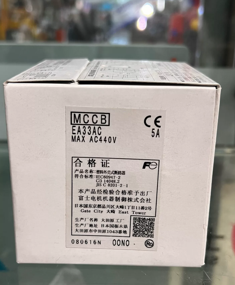
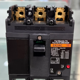
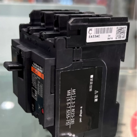
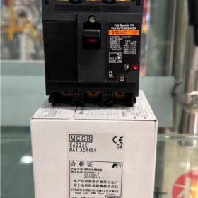
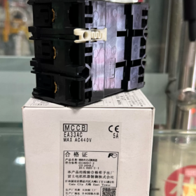
EA33M-3P 32A / EA33AC (A variante EA33AC não tem classificação 32A de fábrica). EA3AAC3P-32A é uma abreviatura manuscrita usada em desenhos & listas de equipamentos. Nome completo: Fuji DISJUNTOR AUTOMÁTICO FUJI EA33M 3P 32A Disjuntor em caixa moldada (MCCB)
- Explicação do código do modelo
EA33: 30Tamanho do quadro AF (corrente nominal máxima 32A para este quadro)
M: Tipo padrão, disparo termomagnético para proteção de distribuição de energia
3P: 3-pólo, trifásico
32UM: Corrente operacional nominal In = 32A
Observação: A classificação máxima da série EA33AC é de apenas 30A; nenhuma versão 32A genuína. A designação oficial da variante 32A é EA33M 3P 32A.
- Especificações elétricas principais
| Item | Parâmetro |
| Modelo | EA33M 3P 32A (corresponde à abreviatura do desenho EA3AAC3P-32A) |
| Poloneses | 3P, trifásico de três fios |
| Corrente nominal em | 32UM |
| Tensão nominal de isolamento Ui | AC415V |
| Tensão operacional nominal Ue | AC220V / AC380/415V |
| Capacidade máxima de ruptura Icu | 2.5ka@AC220V; 1.5ka@AC415V (Padrão JIS) |
| Unidade de viagem | Viagem Termomagnética (Atraso de longo prazo para sobrecarga + disparo instantâneo por curto-circuito) |
| Padrões | ELE C8201, IEC60947-2 |
| Origem | Eletro Fuji, Japão (Modelo importado mais antigo) |
- Informações importantes
- Status do produto: Descontinuado
A série EA33 é um MCCB compacto de geração mais antiga, produção encerrada permanentemente pela Fuji.
Modelo de substituição direta: BW32AAG-3P 32A, dimensões de montagem e layout de terminal idênticos, plug-and-play intercambiável.
- Dimensões Físicas (L × A × P)
Aprox.. 75mm × 130 mm × 60 mm, tipo fixo com fio frontal.
- Cenários típicos de aplicação
Circuitos ramificados de energia trifásicos dentro de pequenos gabinetes de controle, circuitos de energia de máquinas-ferramenta, fãs & alimentadores de carga de bomba de água.
Não é adequado para circuitos com alta corrente potencial de curto-circuito (capacidade máxima de interrupção limitada a 2,5kA).
- Fornecimento & Recomendação de substituição
Usado / estoque excedente: EA33M-3P 32A (disponibilidade limitada)
Para novos projetos & modernização de equipamentos: BW32AAG-3P 32A (Produção atual da série G-TWIN da Fuji Electric)
Guia de instalação completo para Fuji EA33M 3P 32A (EA3AAC3P-32A)
Modelo de unidade física: EA33M 3P 32A, desenho taquigráfico EA3AAC3P-32A. MCCB Fuji 30AF legado, montagem fixa com fio frontal padrão; não é possível prender diretamente no trilho DIN de 35 mm.
⚠️ Requisitos de segurança pré-trabalho
- Isole completamente a fonte de alimentação a montante e verifique a tensão zero antes de qualquer fiação & trabalho de instalação;
- O trabalho deve ser realizado por eletricistas qualificados;
- Ambiente de instalação: Evite poeira pesada, umidade, gás corrosivo e luz solar direta. Faixa de temperatura ambiente de operação: -5℃ ~ +40 ℃;
- O disjuntor deve ser instalado verticalmente (alça se move para cima e para baixo). A montagem horizontal ou invertida é proibida, o que causará falha no mecanismo de disparo.
Papel 1: Procedimento de montagem mecânica
- Recortar & Dimensões de montagem EA33M 3P
Dimensões gerais: L75mm × A130mm × D60mm
Dois furos de montagem inferiores: φ4,5mm, espaçamento horizontal entre furos 54mm; Fixado na placa de montagem com parafusos M4.
❗ Nota Crítica: Este modelo não possui trava de trilho DIN integrada. A montagem direta em trilho DIN padrão de 35 mm é impossível. Suporte adaptador especial necessário para montagem em trilho DIN (raramente disponível no mercado).
- Operação de montagem
- Coloque o MCCB contra a placa de montagem e mantenha o alinhamento vertical;
- Aperte os parafusos M4 superiores e inferiores uniformemente. Não aperte demais um lado para evitar deformação do alojamento;
- Após a fixação, alterne a alavanca ON/OFF repetidamente para confirmar a operação suave sem emperrar.
Papel 2. Especificação de fiação elétrica (Conexão frontal)
- Definição de terminal (Consulte a marcação da unidade)
Terminais superiores: Lado da linha (Entrada de energia) → Conectar alimentação trifásica L1/L2/L3
Terminais Inferiores: Lado de carga (Saída de potência) → Conectar motores & equipamento final
✅ Fiação padrão: Fornecimento de cima, carga na parte inferior
Aviso: Fiação reversa (energia alimentada por baixo) não é recomendado para este modelo legado. A fonte de alimentação reversa reduz a capacidade de interrupção de curto-circuito e introduz riscos de segurança durante falhas.
- Especificação do cabo & Torque de aperto
Tamanho de cabo recomendado para 32A: 6condutor de cobre mm². Use terminais de cabo OT/UT; fios trançados desencapados não devem ser inseridos diretamente nos terminais.
Tamanho do parafuso terminal: M5
Torque de aperto recomendado: 2.0~2,5 N·m
Torque insuficiente → superaquecimento & terminais queimados; Torque excessivo → desgaste da rosca, base de plástico rachada.
- Etapas de fiação
- Controlar o comprimento de decapagem do fio; os fios de cobre expostos não devem se estender além dos terminais ou entrar em contato com fases adjacentes;
- Os terminais de cabo devem se encaixar totalmente na superfície do terminal. Evite a tensão lateral do cabo aplicando carga mecânica contínua aos terminais;
- Conecte três fases sequencialmente e combine a sequência de fases;
- Verifique novamente o torque em todos os parafusos do terminal após a conclusão da fiação.
Papel 3. Lista de verificação de inspeção pré-energização
- Confirme a alça posicionada em OFF (Abrir);
- Use o multímetro para confirmar que não há curto-circuito entre fases e nenhum curto-circuito fase-terra;
- Mantenha folgas suficientes entre as fases; barreiras de fase devem ser instaladas dentro de gabinetes metálicos, se necessário;
- Limpe todas as aparas de metal e restos de fios soltos dentro do gabinete para evitar curto-circuito.
Papel 4. Comissionamento & Energizante
- Confirme se não há pessoal trabalhando no lado da carga antes de energizar a alimentação a montante;
- Mude a alavanca para a posição ON. Fique atento a ruídos anormais, fumaça ou superaquecimento;
- Execute sob carga por 30 minutos. Verifique a temperatura terminal; nenhum aumento excessivo de temperatura anormal indica instalação aceitável.
- Sobrecarga & testes de curto-circuito só são permitidos em ambiente de laboratório. Testes deliberados de curto-circuito no local são proibidos.
Papel 5. Operações Críticas Proibidas (Armadilhas Comuns)
- ❌ Proibir instalação horizontal ou invertida
- ❌ Proibir fiação direta com fios soltos sem terminais de cabo
- ❌ Proibir operação de longo prazo com alimentação reversa (entrada inferior)
- ❌ Não puxe os cabos com força para aplicar tensão mecânica aos terminais do disjuntor
- ❌ Não instale diretamente em ambientes com alta umidade & condensação sem invólucro de proteção
- ❗ Este modelo foi descontinuado com peças de reposição limitadas. Substitua por BW32AAG-3P32A para novas instalações (troca direta compatível com tamanho).
Papel 6. Solução básica de problemas durante o comissionamento
Disparo instantâneo ao fechar: Falha de curto-circuito no circuito a jusante
Disparo após operação com carga sustentada: Terminais soltos causando calor ou sobrecarga de carga
A alça não pode ser fechada: Mecanismo interno apreendido; disjuntor danificado, não ataque ou force a operação
Falhas Comuns, Causas & Soluções para MCCB Fuji EA33M 3P 32A
Nota sobre equipamento: EA33M é o legado MCCB termomagnético Fuji 30AF. A longa vida útil geralmente leva ao envelhecimento da trava mecânica e da tira bimetálica interna; muitas falhas se originam da deterioração de componentes.
Falta 1: Difícil de fechar / Não é possível travar, alça presa na posição intermediária
Sintomas
A alça não pode ser empurrada totalmente para a posição LIGADA e não consegue permanecer travada; recupera imediatamente após o lançamento.
Causas Raiz
- Mecanismo livre de desarme acionado e não redefinido
Depois de tropeçar, o disjuntor entra no estado livre de desarme. A alavanca deve ser firmemente empurrada totalmente para baixo até a posição limite DESLIGADO para reinicialização antes de fechar novamente.
- Curto-circuito sustentado ou sobrecarga severa no circuito a jusante, desencadeando disparo magnético instantâneo imediatamente após o fechamento.
- Envelhecimento a longo prazo: fadiga interna da mola, desgaste da trava, bloqueio mecânico.
- Inclinação de montagem ou vibração excessiva do gabinete causando desalinhamento do mecanismo (montagem vertical obrigatória).
Procedimento de solução de problemas
- Corte a fonte de alimentação upstream, empurre a alça firmemente até o limite OFF para redefinir e tente fechar novamente;
- Desconecte todos os cabos de carga nos terminais inferiores, realizar teste de fechamento sem carga:
✅ Fecha com sucesso sem carga → Existe falha na fiação ou equipamento a jusante
❌ Ainda não fecha sem carga → Danos internos no MCCB, substitua a unidade diretamente
- Verifique a montagem vertical; adicione medidas de amortecimento de vibração se o gabinete sofrer vibração severa.
Falta 2: Tropeço espontâneo após correr por um período (Disparo retardado)
Sintomas
Começa normalmente, viagens após dezenas de minutos a várias horas de operação, nenhum estrondo alto de curto-circuito.
Classificação das Causas
- Disparo por sobrecarga (ativação de disparo térmico)
Corrente operacional contínua próxima ou superior a 32A; cabos subdimensionados, motor envelhecido, sobrecarga combinada de vários equipamentos.
- Terminais soltos geram calor, o calor é transferido para a tira bimetálica interna e desencadeia um falso desarme térmico (Falha de campo mais frequente!)
Parafusos terminais M5 soltos devido a torque insuficiente & vibração → superaquecimento do terminal → condução de calor interna causa disparo indesejado.
- Envelhecimento MCCB: Tira bimetálica fatigada, característica de viagem deslocada, tropeça falsamente sob leve aumento de temperatura.
- Má ventilação do gabinete e temperatura ambiente excessiva.
Ações Corretivas
- Meça a corrente operacional trifásica com um alicate amperímetro para confirmar se a corrente excede 32A; reduza a carga ou atualize o dispositivo de proteção se estiver sobrecarregado.
- Desligue e reaperte todos os terminais com o torque especificado (2.0~2,5 N·m); substitua os terminais do cabo, se necessário.
- Melhorar o layout de refrigeração do gabinete; evite montar vários componentes geradores de calor adjacentes uns aos outros.
- Se ocorrerem disparos retardados frequentes sob corrente de carga normal → envelhecimento do disjuntor, substituição recomendada.
Falta 3: Disparo instantâneo imediatamente após o fechamento
Sintomas
O disjuntor desarma instantaneamente ao fechar, não pode sustentar a conexão de carga.
Causas
- Curto-circuito fase-fase ou curto-circuito fase-terra no lado da carga (isolamento do cabo danificado, curto-circuito no enrolamento do motor)
- Falha à terra no equipamento de carga
- Quebra interfase interna dentro do MCCB (dano permanente à unidade)
Fluxo de solução de problemas
- Desconecte todos os cabos de carga de saída, realizar teste de fechamento sem carga
Fecha normalmente sem carga → Falha no cabo ou motor a jusante; teste de isolamento com megômetro
Ainda desliga instantaneamente sem carga → Avaria interna do MCCB, interrompa o uso e substitua imediatamente
Falta 4: Superaquecido & terminais de conexão descoloridos
Sintomas
A temperatura terminal aumenta significativamente durante a operação, o isolamento do cabo amolece, superfície terminal escurece.
Causas
- Torque de aperto insuficiente levando a alta resistência de contato
- Não há terminais de cabos instalados, fios soltos criam mau contato
- Operação contínua em plena carga com condutores subdimensionados (Cobre mínimo de 6mm² recomendado para 32A)
- Oxidação e acúmulo de poeira nos terminais.
Ações Corretivas
- Isolar a fonte de alimentação, camada de oxidação limpa, instale novos terminais de cabo OT;
- Reaperte os terminais com o torque especificado;
- Se os terminais estiverem gravemente queimados e a base plástica deformada pelo calor: MCCB deve ser substituído, operação continuada proibida.
Falta 5: Perda de fase / Nenhuma saída em uma fase enquanto a alavanca permanece fechada
Sintomas
A alça mostra a posição fechada, tensão presente no terminal de entrada superior, mas nenhuma saída no terminal inferior para uma fase.
Causas
Cada pólo do EA33M possui contatos independentes. Aquecimento prolongado e erosão do arco levam à separação de contato ou soldagem parcial em pólo único.
⚠️ Perigo Grave! Disjuntor visivelmente fechado com fase interna aberta queimará facilmente motores trifásicos.
Remédio
Desligue e teste a continuidade entre os terminais superior e inferior para cada fase. Substitua o disjuntor imediatamente se alguma fase falhar no teste de continuidade; o reparo no local não é viável.
Falta 6: O disjuntor não funciona após um evento de curto-circuito
Sintomas
Não pode ser fechado ou funciona continuamente quente após desarme devido a curto-circuito.
Causas
Alta corrente de curto-circuito cria arco elétrico, queimando permanentemente os contatos principais e danificando o mecanismo de disparo interno.
Nota importante
EA33M tem baixa capacidade de interrupção (1.5ka@AC415V). One high-magnitude short-circuit can permanently damage the unit.
✅ Solução: After clearing short-circuit fault, replace the breaker rather than continuing operation with damaged components.
Standard Field Troubleshooting Sequence
- Isolate power supply → Push handle fully down to OFF position for complete reset
- Disconnect all load cables, test breaker performance under no-load
- Locate fault source: Distinguish between downstream wiring/equipment fault and internal MCCB failure
- Damaged breakers cannot be repaired; direct replacement model: BW32AAG-3P 32A (Direct dimensional interchange)
Critical Operational Warnings
- EA33M series has been discontinued. Risk of component aging rises with service time; not recommended as primary protection for critical equipment.
- Fiação reversa (power fed from lower terminals) não é recomendado. Reduz a capacidade de interrupção de curto-circuito e aumenta o risco de falha.
- Não bata ou force a alavanca de operação para tentar fechar, que pode bloquear permanentemente o mecanismo interno.







NH42-63-318x560.png "Chaves de transferência automática tipo PC CHINT (ATS)NH42-63/4SZ")



