 Schütz,Leistungsschalter,Solarwechselrichter,Stromzähler,Solarbatterien

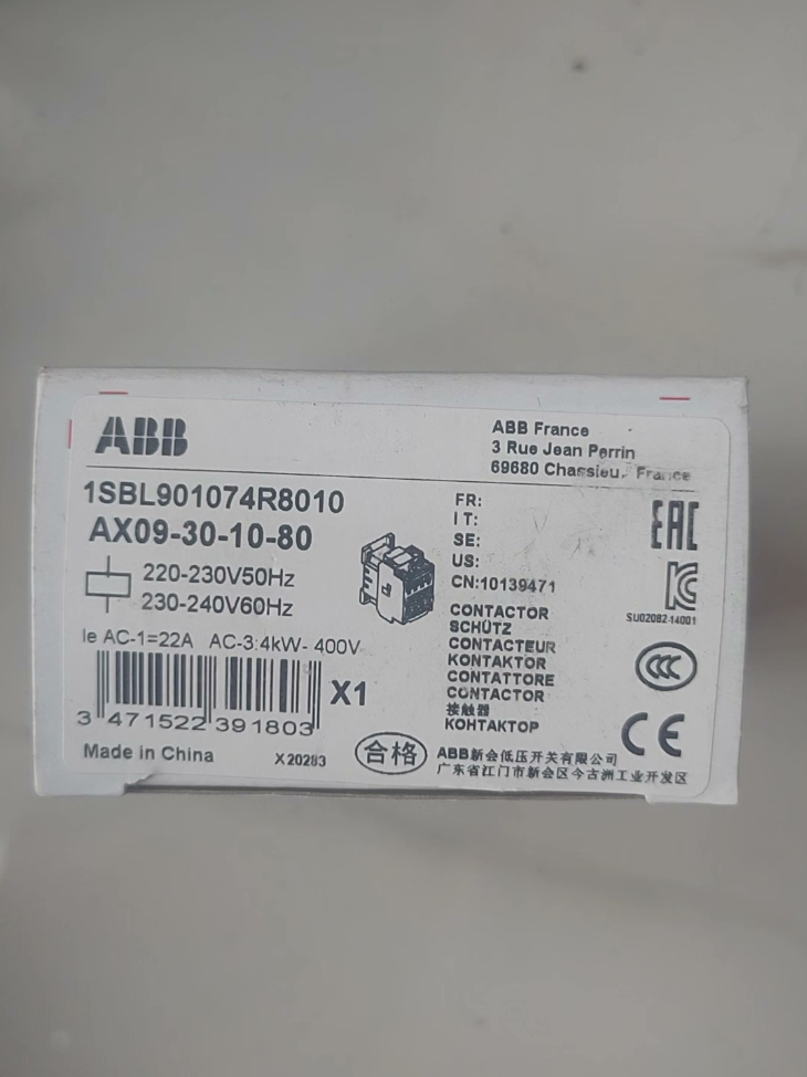

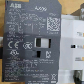
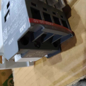
The AX09-30-10-80 is a general-purpose 3-Pol-AC-Schütz von ABB AX series, der offizielle Nachfolger des klassischen A9-Schützes aus der ehemaligen A-Serie. It is designed for controlling low-power loads in general industrial applications, mainly used for direct start and stop of three-phase asynchronous motors, as well as switching of AC distribution circuits, inductive and resistive loads.
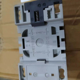
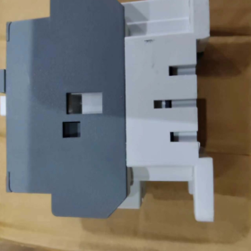
Equipped with a conventional AC coil, this contactor features compact structure and small footprint. It supports mounting on standard 35 mm DIN rails, and offers long mechanical service life, high operating frequency and excellent environmental adaptability. It is widely applied in building HVAC systems, light automation systems, OEM equipment assembly, municipal power distribution and other fields.
- Interpretation des Modellcodes
Vollständiges Modell: AX09-30-10-80
- AXT: Seriencode, representing AX series general-purpose AC contactors (replacement for legacy A series).
- 09: Rated current class. Rated operational current is 9 A under utilization category AC-3 at 400 V.
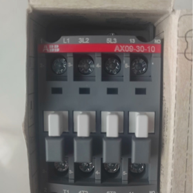
- 30: Main contact configuration. 3 normally open main contacts with no normally closed main contacts (the first digit = number of main poles; the second digit = number of normally closed main contacts).
- 10: Hilfskontaktkonfiguration. 1 normally open auxiliary contact with no normally closed auxiliary contacts (the first digit = number of normally open auxiliary contacts; the second digit = number of normally closed auxiliary contacts).
- 80: Coil code, corresponding to standard AC coil: 220-230 V und 50 Hz / 230-240 V und 60 Hz.
- Technische Kernparameter
3.1 Hauptstromkreisparameter
| Artikel | Spezifikation |
| Polen & Kontaktkonfiguration | 3P, 3 Normally Open main contacts |
| Konventioneller thermischer Strom (Ith) | 24 A (Ambient temperature ≤ 40 ℃) |
| Nennbetriebsstrom (AC-1) | 22 A (≤ 690 V und, ≤ 40 ℃); 18 A (≤ 70 ℃) |
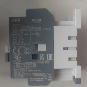
| Nennbetriebsstrom (AC-3) | 9 A (≤ 440 V und, ≤ 55 ℃); 7 A (≤ 690 V und, ≤ 55 ℃) |
| Maximum Rated Operational Voltage (Ue) | 690 V und |
| Rated Control Power (AC-3) | 4 kW @ 400 V; 5.5 kW @ 690 V |
| Bewertete Ausschaltkapazität (AC-3) | 8 × Ie |
| Bewertete Stoßspannungsfestigkeit (Ump) | 6 kV |
| Overvoltage Category | Category III |
| Hauptstromkreisanschluss | Screw terminal connection, suitable for solid/stranded copper conductors |
| Torque for Main Terminals | 1.2 ~ 1.5 N·m |
3.2 Parameter des Steuerkreises
| Artikel | Spezifikation |
| Rated Coil Voltage (Uc) | 220~230 V AC 50 Hz; 230~240 V AC 60 Hz |
| Aufnahmespannungsbereich | 0.85 Uc ~ 1.1 Uc |
| Dropout-Spannungsbereich | 0.2 Uc ~ 0.75 Uc |
| Coil Type | Conventional AC excitation coil |
| Standard Auxiliary Contact | 1 NEIN, compatible with AC-15 / DC-13 control circuits |
| Rated Capacity of Auxiliary Contact | AC-15: 10 A / 220 V; DC-13: 0.55 A / 220 V |
| Anschluss des Steuerkreises | Schraubklemmen |
3.3 Mechanisch & Umgebungsparameter
| Artikel | Spezifikation |
| Gesamtabmessungen (B × H × T) | 44 mm × 74 mm × 74 mm |
| Nettogewicht | Ca. 0.326 kg |
| Schutzklasse | IP20 (main body) |
| Betriebsumgebungstemperatur | -25 ℃ ~ +55 ℃ (Full rating within 55 ℃; current derating required at 70 ℃) |
| Installationshöhe | No current derating up to 3000 M |
| Montagemethode | Standard 35 mm DIN-Schienenmontage; vertical screw mounting available |
| Zertifizierungen | IEC 60947-4-1, CCC, CE, UL, RoHS |
3.4 Lebensdauer & Leistungsparameter
| Artikel | Spezifikation |
| Mechanisches Leben | 10,000,000 Betriebszyklen |
| Elektrisches Leben (AC-3-Dienst) | 1,000,000 Betriebszyklen |
| Maximale Betriebsfrequenz | 1200 Zyklen pro Stunde |
| Pick-up Time | 7 ~ 21 MS |
| Drop-out Time | 4 ~ 11 MS |
- Alternative Modelle & Cross-Series Reference
4.1 ABB Equivalent Replacements
- Replacement for Discontinued Models: Direct replacement for legacy A series A9-30-10. Fully compatible with original mounting holes and rail dimensions, with upgraded electrical life and overall reliability.
- Same Current Rating with Different Coils:
AX09-30-10-81: 24 V und 50/60 Hz coil
AX09-30-10-84: 110 V und 50 Hz / 110~120 V 60 Hz coil
AX09-30-01-80: Same main circuit, fitted with 1 NC-Hilfskontakt
- Higher Current Models in the Same Series: AX12-30-10-80 (12 A), AX18-30-10-80 (18 A). Identical mounting width for direct replacement and capacity upgrade.
4.2 Equivalent Products from Other Brands
Schneider Electric: LC1D09M7C
Siemens: 3RT6015-1AN21
Chint: NXC-09 (220 V-Spule)
> Notiz: All cross-brand models support 35 mm DIN rail mounting for direct replacement. Please verify auxiliary contact configuration and coil voltage before installation.
- Full List of AX Series 3-Pole Contactors (220 V Coil)
| Modell | Nennstrom (AC-3 @ 400 V) | Corresponding Motor Power @ 400 V | Standard Auxiliary Contacts |
| AX09-30-10-80 | 9 A | 4 kW | 1 NEIN |
| AX12-30-10-80 | 12 A | 5.5 kW | 1 NEIN |
| AX18-30-10-80 | 18 A | 7.5 kW | 1 NEIN |
| AX25-30-10-80 | 25 A | 11 kW | 1 NEIN |
| AX32-30-10-80 | 32 A | 15 kW | 1 NEIN |
| AX40-30-10-80 | 40 A | 18.5 kW | 1 NEIN |
| AX50-30-11-80 | 50 A | 22 kW | 1 NEIN + 1 NC |
| AX65-30-11-80 | 65 A | 30 kW | 1 NEIN + 1 NC |
| AX80-30-11-80 | 80 A | 37 kW | 1 NEIN + 1 NC |
| AX95-30-11-80 | 95 A | 45 kW | 1 NEIN + 1 NC |
Gemeinsames Zubehör
Thermisches Überlastrelais: TA25DU series (z.B. TA25DU-9M). Direct plug-in bottom mounting for motor overload protection.
Auxiliary Contact Blocks: CA5X series front-mounted modules (CA5X-10E, CA5X-01E, CA5X-22E), erweiterbar bis zu 4 pairs of auxiliary contacts.
Überspannungsschutz: RV5X series, absorbs switching overvoltage of coils to protect PLC control circuits.
Mechanische Verriegelung: VB5X series, provides mechanical interlock for forward/reverse operation of two contactors.
Terminal Shroud: Improves protection level and prevents accidental contact.
- Anwendungsbereich & Operating Limits
6.1 Typische Anwendungen
- Small Motor Control: Direct start/stop of three-phase asynchronous motors such as small fans, Wasserpumpen, Förderer, roller table motors and mini compressors, suitable for loads up to 4 kW.
- Gebäude & HVAC-Systeme: Control of terminal units of central air conditioning, fresh air units, fire exhaust fans, water supply & drainage pumps and fire dampers. It acts as a key actuator for power distribution circuits in building automation.
- OEM-Ausrüstung: Power circuit control for packaging machinery, Textilmaschinen, small machine tools, food processing equipment and other automated machinery. The compact size saves cabinet space.
- Stromverteilung & Lichtsteuerung: Remote switching of high-capacity lighting circuits and small distribution feeders; switching of low-capacity capacitor banks in low-voltage reactive power compensation cabinets.
- Automation Logic Control: Acts as a power amplifier for PLC outputs to drive solenoid valves, indicator lights and other small actuators.
6.2 Umweltanforderungen
Install indoors inside switchgear or control boxes. Outdoor exposure to rain and direct sunlight is prohibited.
Pollution level shall not exceed Class 3; no highly corrosive gas, explosive gas or conductive dust present.
No severe impact or vibration on mounting surface; vibration acceleration ≤ 20 m/s².
Current derating is required when installation altitude exceeds 3000 m or ambient temperature exceeds 55 ℃, refer to official manual for calculation.
- Troubleshooting Matrix
| Fehlerphänomen | Grundursache | Lösungen |
| Contactor fails to close with no sound | 1. Keine Stromversorgung, loose or broken wiring in control circuit | 1. Cut off power and perform safety check; inspect wiring at terminals A1/A2 and re-measure coil voltage |
| 2. Burnt or broken coil | 2. Test coil resistance with multimeter; replace coil or complete unit if open circuit occurs | |
| 3. Armature mechanical jam or foreign obstruction | 3. Manually operate armature after power-off, clean dust and foreign matters on core pole faces | |
| 4. Supply voltage far below rated value | 4. Adjust supply voltage to rated range and eliminate line voltage drop | |
| Continuous buzzing noise after closure | 1. Oil and dust on core pole faces causing poor contact | 1. Dismantle core after power-off and clean oil & dirt on pole faces |
| 2. Broken or detached shading coil | 2. Replace core or complete unit if shading coil is damaged | |
| 3. Insufficient suction due to low supply voltage | 3. Increase supply voltage to rated range | |
| Abnormal overheating at main terminals / Kontakte | 1. Loose terminal screws leading to high contact resistance | 1. Retighten terminals to specified torque after power-off |
| 2. Continuous overload with current exceeding rated value | 2. Laststrom messen, check model selection and replace with higher-rated model if necessary | |
| 3. Contact ablation and poor conduction | 3. Polish slightly ablated contacts; replace complete unit for severe damage | |
| Abnormal signal from auxiliary contacts, no feedback to PLC | 1. Ablation or poor contact of auxiliary contacts | 1. Test on-off performance of auxiliary contacts after power-off and replace faulty blocks |
| 2. Loose or broken cables | 2. Inspect wiring and PLC input circuit to fix line faults | |
| 3. Improper installation of auxiliary contact block | 3. Reinstall auxiliary contact block and ensure firm connection | |
| Severe coil overheating, burning smell or smoke | 1. Supply voltage exceeds coil rating | 1. Cut off power immediately, verify supply voltage and rule out wrong high-voltage connection |
| 2. Coil inter-turn short circuit | 2. Spulenwiderstand messen; replace coil if inter-turn short circuit is confirmed | |
| 3. Long-term operation under undervoltage condition with excessive current | 3. Maintain supply voltage within rated range and avoid prolonged undervoltage operation | |
| Failure to open or slow release after power cut | 1. Adhesion caused by oil on core pole faces | 1. Clean oil on core pole faces and check residual magnetism |
| 2. Welded main contacts | 2. Inspect main contacts after power-off; replace contacts or complete unit if welding occurs | |
| 3. Fatigue failure of return spring | 3. Replace return spring or complete contactor |


, Spulenspannung von 110V AC, und ist ausgestattet mit 1 Normalerweise geöffnet (1NEIN) Hilfskontakt")
. Empfohlener Ersatz: LC1D115KUEC oder LC1E120M5N")


AC-Schütz der CHINT Kunlun-Serie, verbesserte kompakte Struktur, die die traditionelle CJX2-Serie ersetzt")

")
NH42-63-318x560.png "Automatische Transferschalter vom Typ CHINT PC (ATS)NH42-63/4SZ")


